Introduction
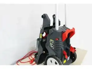
This guide will take you through the steps of replacing your Sterwins HC 150's pump.
-
-
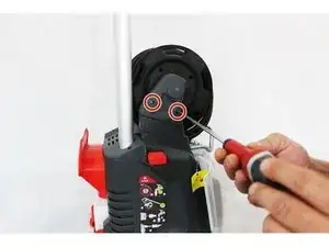
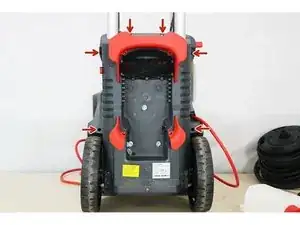
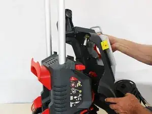
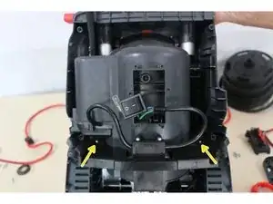
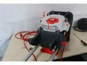
Unscrew the 2 housing fixing screws.
-
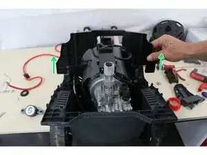
Remove the housing.
-
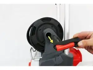
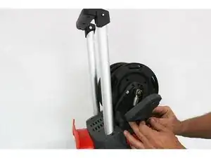
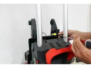
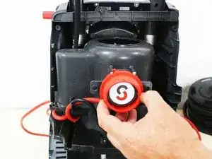
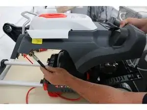
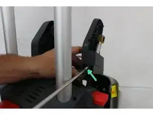
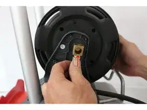
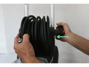
Using a flathead screwdriver, remove the clips holding the high pressure outlet connector from the pump to the hose reel.
-
-
-
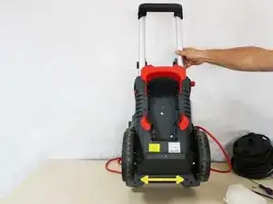
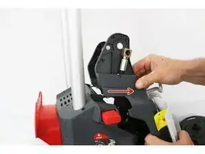
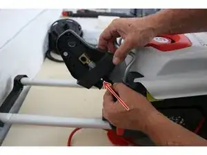
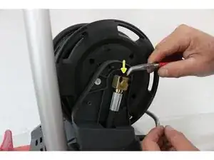
Pull the connection towards you.
-
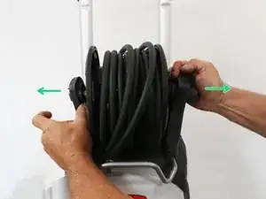
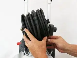
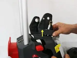
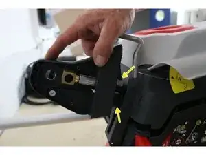
Move the 2 roller bearings outwards.
-
Then remove the winder one side at a time.
-
-
-
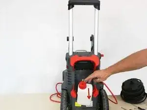
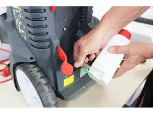
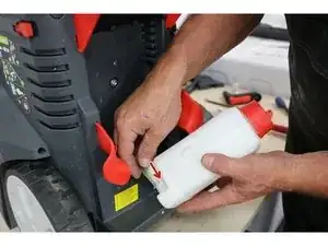
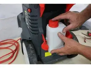
Unhook the container by pulling towards you.
-
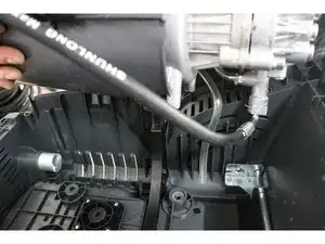
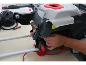
Uncouple the suction hose by pulling in the direction of the arrow.
-
-
-
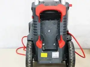
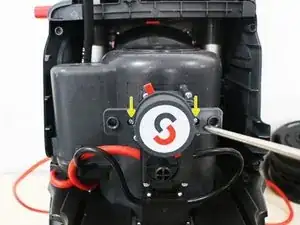
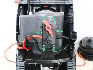
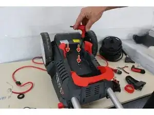
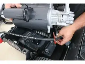
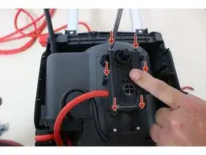
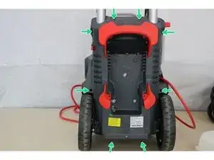
Unscrew the 6 fixing screws indicated by the arrows.
-
Tilt the product forwards to access the last 2 fixing screws located under the device marked with the arrows.
-
Then lay the device flat, and unscrew the plastic nut from the water inlet pipe.
-
-
-
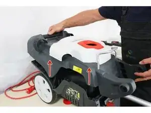
Remove the faceplate upwards.
-
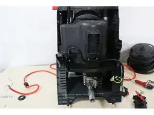
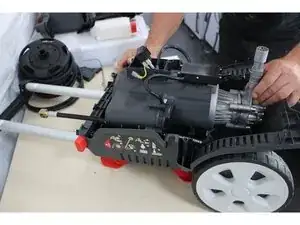
Return the device to an upright position on its wheels.
-
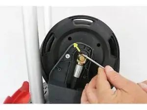
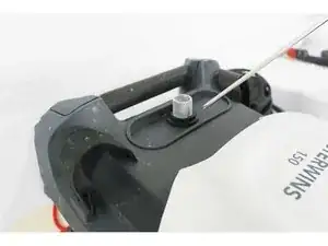
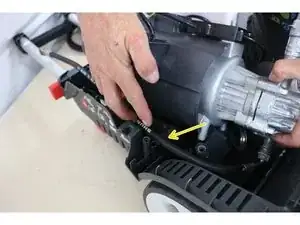
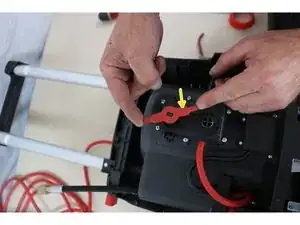
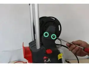
Unscrew the screw indicated by the arrow to separate the bearing from the winder in order to extract the pump outlet pipe.
-
-
-
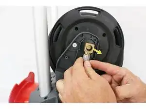
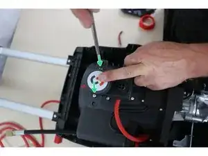
Once the fixing screw removed, slide the bearing as indicated by the arrow.
-
Then pull upwards to extract the bearing from the pipe.
-
Then remove the front panel.
-
-
-
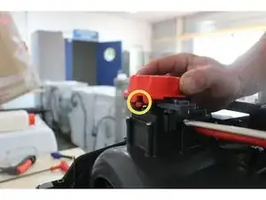
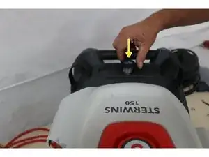
Remove the button facing you.
-
Unscrew the 2 screws as indicated in order to separate the support.
-
Then unscrew the 6 screws and remove the hatch to access the electrical connection.
-
-
-
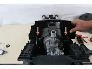
Unscrew the 3 fixing screws of the pump using the allen key.
-
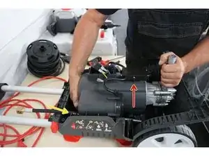
Turn the device over, unscrew the 2 screws of the pump retaining hoop.
-
Then pull it up.
-
-
-
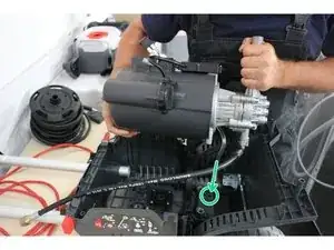
Lift the pump upwards.
-
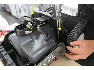
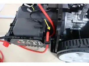
Be careful to note the passage of the high pressure pipe, indicated by the yellow arrow.
-
Be careful to note the passage of the detergent pipe, indicated in green by the arrow and the circle.
-
-
-
Install the pump motor retaining arch.
-
Tighten the 2 arch fixing screws.
-
Turn the device over on the front face in order to reattach the 3 pump motor retaining screws.
-
-
-
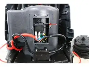
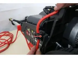
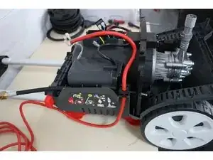
Position the cable block on the housing as indicated by the red arrow.
-
Position the excess cable as indicated by the yellow arrow
-
-
-
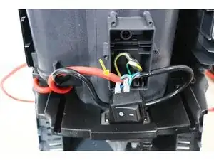
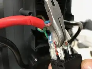
Connect the power cord (red) to the On/Off switch, taking care to match brown with brown (phase) and blue with blue (neutral).
-
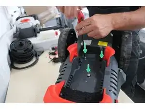
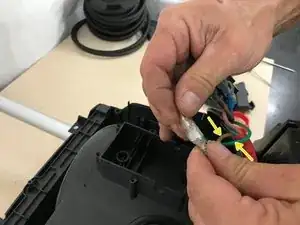
Be careful not to forget to connect the grounding cable (yellow/green) as indicated by the yellow arrows.
-
Reposition the switch in its housing indicated by the orange arrows, as well as the cables indicated by the green arrows.
-
-
-
Position the plate and tighten its 6 fixing screws.
-
Put the control lever back in place.
-
Insert the 2 fixing screws of the button support.
-
-
-
Be careful before fitting the front panel, do not forget the control button by positioning its notch with the control lever (as shown in the photo).
-
Insert the hose into the channel of the bearing support of the reel.
-
-
-
Insert the pipe into the bearing.
-
Insert the slide of the support into that of the front.
-
Put the fixing screw back in place.
-
-
-
Reposition the front panel, aligning the notches correctly.
-
Screw the plastic nut of the water inlet pipe back on.
-
Tighten the 8 front fixing screws.
-
-
-
Connect the hose to the winder.
-
Install the locking clips.
-
Tighten the 2 casing fixing screws
-
-
-
Connect the suction hose to the detergent container.
-
Replace the container.
-
Insert the handle into the winder until it snaps into place.
-

By the end of the guide your pump should be replaced and fully functional.