Introduction

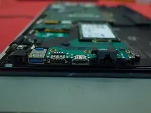
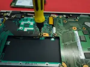
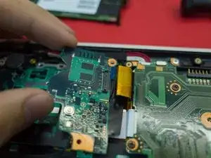
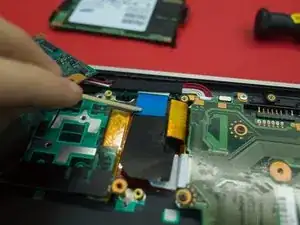
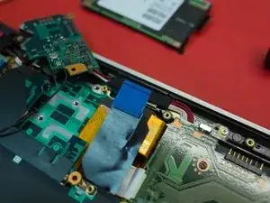
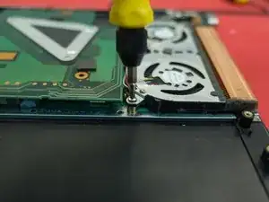
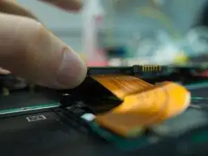
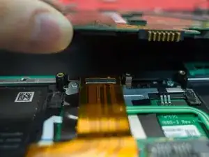
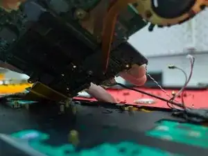
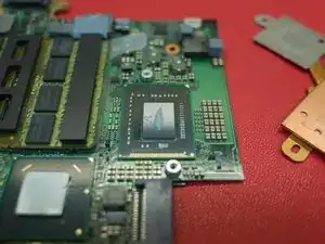
This dissasembly guide was made in the process of changing out a faulty fan unit. To access this fan the motherboard needs to be removed, as well as most other parts of the laptop. If you need to repair or replace the keyboard, this guide should get you most of the way there.

I had initially changed the fan out, but not put the thermal paste on the CPU correctly. This resulted in high fan speeds, as the laptop was compensating for the poor heat dispersion.

Before you start this project, I would suggest reading this whole guide through. Understanding what things look like on the inside will make it much easier to take the laptop apart.

  1. CCC1EJRgHsYdJRJE
    • I wore an anti-static strap and band for this whole process. DO NOT ATTEMPT THIS REPAIR WITHOUT PROPPER ANTI-STATIC PRECAUTIONS. It is incredibly easy to cause damage to your computer with static - do not take a shortcut with this.

    • This laptop had been recently upgraded from Windows 7 to Windows 10. This process was fairly straightforward, and the laptop works perfectly now. A key element of this was finding and installing the various drivers to suit.

    • In particular, the Intel RAID driver needs to be downloaded from the Intel website, and also the fingerprint drivers need to be found and installed.

  2. sdqDYcEmrMj1GjKa
    sdqDYcEmrMj1GjKa
    6WMn1GG3w31NiPkd
    6ITlVIRHepQIMuRI
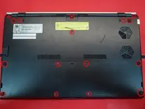
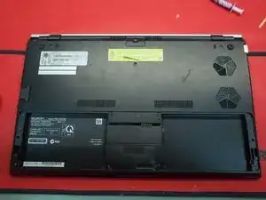
    • Remove the 8 screws holding in the battery

    • Remove the battery

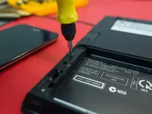
    • Remove all other screws on the underside of the laptop

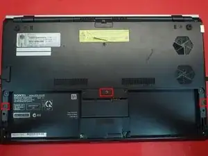
    • Under the battery there are three more screws to remove

    • There are two types of screws (other than the battery screws). In case you lose track; the longer screws go through the rubber feet

  3. WbEswpQekW4mBrKb
    WbEswpQekW4mBrKb
    rA6FWEle5SnRQJCw
    VDPYHEhSfE4I5Iwu
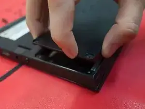
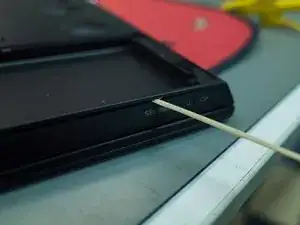
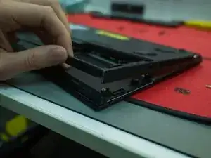
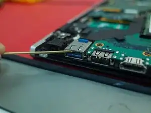
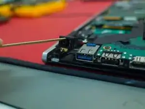
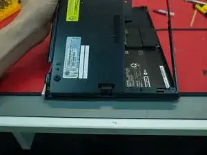
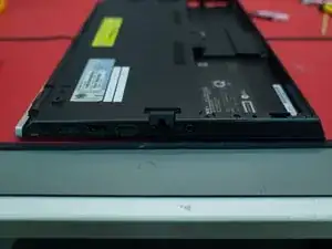
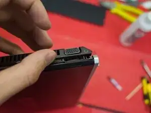
    • Pry the housing apart using something maliable (I used a bamboo stick)

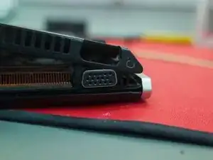
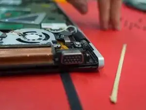
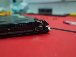
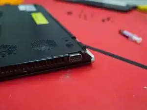
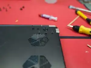
    • Start at the front edge on the side with the VGA port & fan hole

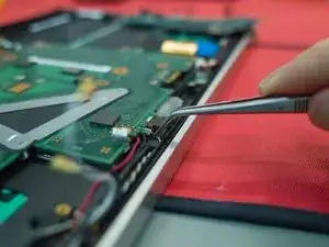
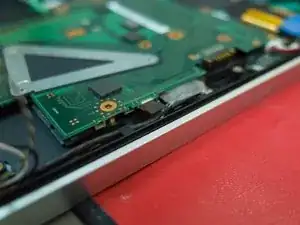
    • The VGA port is not fixed to the chassis, and can be lifted up to assist with removing the case

    • I have shown the VGA port in more detail later in this guide

  4. XAjyCEJ5lquhGxVD
    XAjyCEJ5lquhGxVD
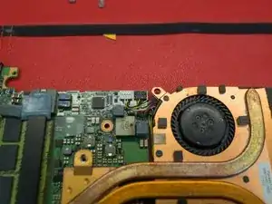
    bFMGVfmHq3G4qEb1
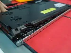
    • Work your way around the back edge of the laptop. The case is held in by small clips which should pop away from the chassis easily.

    • I recommend using the same maliable piece of bamboo or plastic spudger for this task.

  5. qoY1ONvAaK5vAS2f
    qoY1ONvAaK5vAS2f
    TUPYLRX3LOZE1uNQ
    4GpwQW1BVlepgTd2
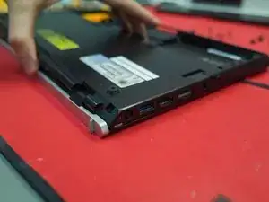
    • Working your way around the other side of the laptop, the case should slide easily over the ports (HDMI/USB etc.)

    • You may need to lift the Ethernet port flap

    • The headphone port, USB 3.0 port, and A/C jack should move freely, and are not directly fixed to the chassis.

  6. mWRRmQSVIR6Nwmji
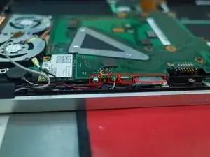
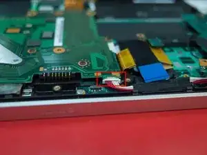
    • As you can see, the VGA port sits in a slot which allows it to move up and down. It is necessary to lift this port when taking the cover off.

  7. yHcgkjS1DMGOMfGs
    yHcgkjS1DMGOMfGs
    G53QnPC6XDAnKGUN
    RZ5LwfrRNByMCZK1
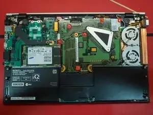
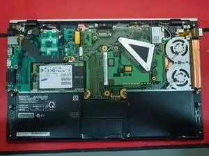
    • Note that screws are marked with an arrow. This is useful when reassembling the laptop, as some screws are not entirely obvious.

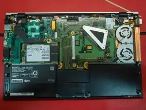
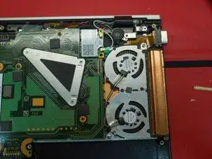
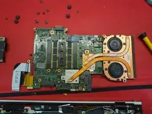
    • On the right is the fan & heatsink

    • The triangle bracket holds in the CPU (accessed from the under side of the motherboard)

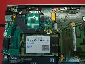
    • The SSD is to the left of the motherboard

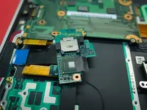
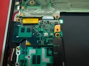
    • Above the SSD is the optical board. This handles the signal for the external dock (PMD), and is responsible for transfering data fast enough to power an external GPU.

  8. ChufSScShPRh5cVR
    ChufSScShPRh5cVR
    jqMkyHxV3HPT1qF1
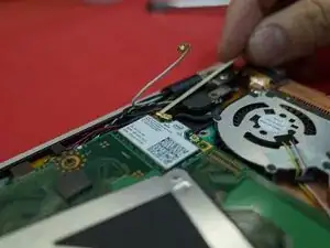
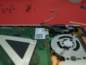
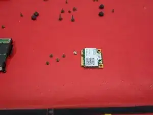
    • Un-plug the two cables holding in the wifi board

  9. TxVoZ3Uj5qK3PSN6
    • Remove the covering for the trackpad to access the plugs attached to the motherboard. This should just slide off.

  10. 2l2lOreXLfpqZ3gV
    2l2lOreXLfpqZ3gV
    Nmf6O6n1wx24FoWu
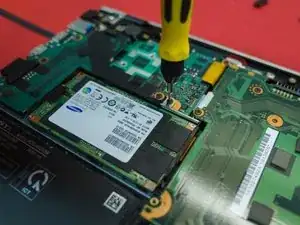
    • Remove the two screws holding in the SSD.

    • Note that the SSD screw also holds in the optical board

  11. TTpDIhm2GLM6uCoC
    TTpDIhm2GLM6uCoC
    aRFairT2OxRZ52xD
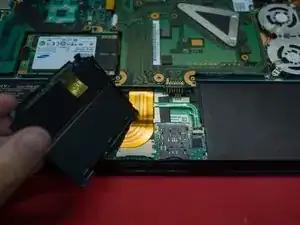
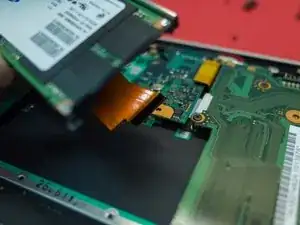
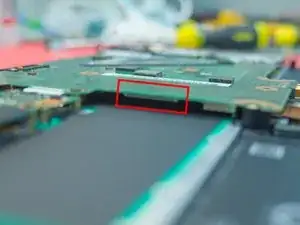
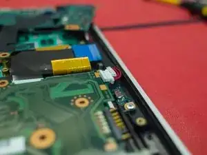
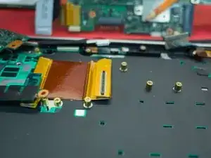
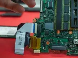
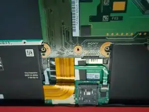
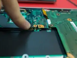
    • The SSD is attached to the motherboard with a flat ribbon cable. This should just pull out.

    • I have over-exposed the second image to highlight where the SSD connector is on the motherboard.

  12. JZQBhBbLohjZDpq1
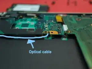
    • Note where the optical signal cable routes along the outside of the SSD bay

  13. giFOI5dxbgM6RToy
    giFOI5dxbgM6RToy
    tUvZosYeSRMgRWvJ
    NXnjbyU4ETeHcobl
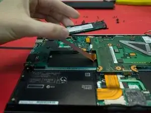
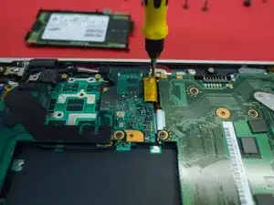
    • Remove the optical board (2 screws)

    • Remove the plug from the optical board to the motherboard (should pull directly up)

  14. GYHUpCApHr6NTNiB
    GYHUpCApHr6NTNiB
    e1Ie4NkXsXgAZfun
    • Hold the blue plastic tab to remove the flat ribbon cable to the motherboard. This should pull straight out horizontally.

  15. p1YckDJvsWPTQeei
    p1YckDJvsWPTQeei
    JgAZc4cBTPwxqHdE
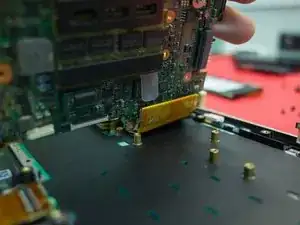
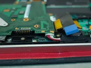
    • On the back edge there are 4 plugs going into the back of the motherboard.

    • I'm not 100% sure, but from the top of my head these are (left to right); speakers (red/black & black/white), VGA (ribbon), and main (flat plug type)

    • There is also a power connector plug on the far side (red/white)

  16. ylcAabEBqkfdYbyW
    ylcAabEBqkfdYbyW
    wF1nJALpBgrdUYH5
    XoVSrLnZZ6Y4SI6a
    • The red/white and black/white plugs are obvious to pull out

    • The VGA cable has a flat plastic tab - pull on this tab to remove/install

    • The red/white power cables are also obvious

    • To remove the main plug, push it straight down towards the keyboard. This is easier to do once the motherboard is free, so I would suggest leaving it in place for now.

  17. MNOVRyFIVCLlRIxb
    MNOVRyFIVCLlRIxb
    gV3XZFCMRH3FixK4
    • Remove the screws holding in the motherboard (6, including the wifi board)

  18. mIQOsFIQvtnkn6m6
    mIQOsFIQvtnkn6m6
    5DRXMAJZu3rfvELY
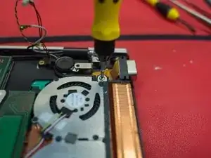
    • Remove the two screws holding in the fan and heatsink

  19. HFSp32MLkGpINNhn
    • The heatsink and fan and connected directly to the motherboard by 3 screws. These screws are attached to the triangle bracket, and are accessible from the under side of the motherboard.

    • This means that the entire motherboard needs to be disconnected to remove the CPU, fan, and heatsink.

  20. RElWGGXgYsnEVxDQ
    RElWGGXgYsnEVxDQ
    VawRnCJJRR6GQ6AG
    • Lift up the edge of the heatsink/fan assembly and identify the remaining connections for the motherboard.

    • Disconnect the trackpad (flat cable, seperates vertically from the board)

  21. WYD2OdH2lDhJjVqs
    • You can see the remaining connectors on the motherboard

  22. 3KdKROQT1Zy4ZUaA
    3KdKROQT1Zy4ZUaA
    feUgcAarSlehryx3
    YEPaACfvxTgF2XKl
    • Underside view of removed motherboard. Here you can see the plug type and RAM

    • Note the plug type for the main motherboard cable (circled)

    • You can also see the three screws for the heatsink and fan assembly.

  23. VXHMFAnAmeYPeZkv
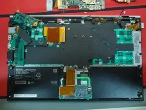
    • Inside view of laptop, motherboard removed. Not much remaining in there now.

  24. EPSD3pmEtYHdanMI
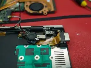
    • View of VGA assembly, speaker, and lid hinge

  25. R4pSBPu3cKEEShpF
    R4pSBPu3cKEEShpF
    g3Npw5qxKCTTnXTi
    cLRG2uqMsmd5gd5i
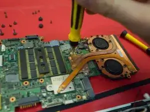
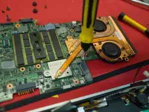
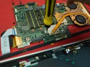
    • Remove the three screws holding on the heatsink and fan assembly.

    • Note; there are two different screw lengths for this assembly

  26. jMJHSeBRmYaxXlD3
    • Unplug the two fan connector (one white, one black)

    • Note; these clip in vertically, not horizontally

  27. cUwyFKheSIBpKVYB
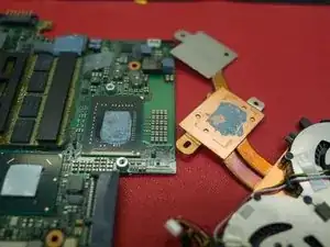
    • Once the fan assembly is disconnected, you can lift it up.

    • Here you'll see the bad job I did on the thermal paste, and the reason why I had to take it apart again.

  28. gLscVMxHTx2X6AiB
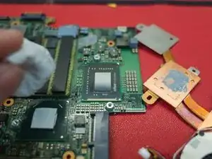
    • Using a clean microfibre cloth and rubbing alcohol, wipe the old thermal paste off the CPU

    • Note: The original paste that was on the CPU was very dry and caked onto the board. Take extreme caution in removing this old paste.

  29. WcZjYnoJCHkT3Xfy
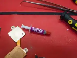
    • New Cooler Master thermal paste

    • It's worth spending the extra couple of bucks on a good brand of paste. It really isn't worth the trouble of having to re-do this (trust me!)

  30. Rwp351BHSX5YUiFn
    • Clean the remaining paste of the heatsink side of the assembly (far right in the picture)

    • Small strip of paste going lengthways on the CPU. You want to avoid air bubbles in the thermal paste.

    • Note: This was actually a bit too much paste. Once you put the heatink and fan assembly on, it will spread out on its own. Avoid the temptation to spread the paste out!

  31. fk3patVylUMrShNU
    • Carefully place the heatsink and fan assembly onto the CPU and attach the three screws.

    • Plug the fan power cables back in (as I mentioned earlier, these should slot straight down into the socket)

  32. UHfWoktARXoiclyw
    UHfWoktARXoiclyw
    tigOBx3QYXtwFkSs
    • I attached the main motherboard cable first, as it was the most dificult in my opinion. You could plug these back up in whichever order suits you.

    • Take your time to make sure that everything is plugged up securely, as you can tell, it's not something you'll want to do a 2nd time.

  33. BrZCRWOfUjIRsHnu
    • Plug up the large flat cable to the motherboard

  34. WxJF4RTLDJZFiNmH
    • Attach the trackpad cable

  35. PiPQUKe1fieddrwL
    • Attach the motherboard power

    • Put the 5 screws back in for the motherboard

    • Put the 2 screws back in for the heatsink and fan assembly

  36. VHIIEorSVBbMEKAc
    VHIIEorSVBbMEKAc
    QBCYaIXgkdcAXtVN
    XFVjvvAxH4xEMiRK
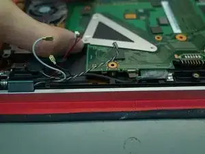
    • Attach the speaker cables & VGA port

    • Note: be careful with the cabling here. Pay attention to how the cables sit, and make sure they are not going to be pinched by other pieces.

    • I actually damaged the VGA cable when I did this the first time. It was a cheap part to fix, but again - be careful, you can damage these parts.

  37. rQf4rMTHZsnWHNWO
    rQf4rMTHZsnWHNWO
    ujXH3thNYIfDT1pE
    • Replace the wifi card and plug up the white and black cables

  38. RLESt5avIdIAiGpn
    • Replace the SSD cable (slides straight into the port on the motherboard)

  39. xNCCUmA5rSnnLMCC
    xNCCUmA5rSnnLMCC
    bvlWHTyLqKNYmCLM
    • Replace the flat ribbon cable to the connector, using the blue plastic strip to push it into the port.

  40. JFSr3A15E5GlYYaS
    JFSr3A15E5GlYYaS
    gPM6Mo5wm2RjlOIB
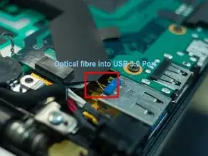
    • This is the optical board. You can see here the two optical fibre cables that go into the USB 3.0 port to communicate with the optional Power Media Dock (PMD).

    • I believe they use fibre for this application because of the bandwidth required to run an external GPU

  41. lucy31Pg6pdHt3eZ
    lucy31Pg6pdHt3eZ
    6YxSrbKgZebAgFJM
    • Replace the two screws holding the optical board.

    • The optical board tends to spring up, and you may need to hold it down while you screw it back in.

    • Pay attention to where that optical cable goes - this is relatively fragile, you don't want it getting caught between a screw or a board.

  42. trXh1KLuoNTwRCCF
    trXh1KLuoNTwRCCF
    ncbH1PF3ZWfANxMw
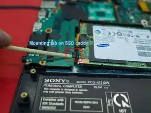
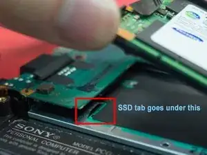
    • The SSD caddy has a notch on the left side. This needs to sit under the housing on the chassis.

  43. iGEYZLFGwXQQAWSe
    • Everything all plugged back up and screwed in.

    • As with before, check the components for the arrows which indicate where the screws go. Those screws in the laptop case actually go through the case into the chassis.

  44. FKKFFcpYOjGPAvBv
    FKKFFcpYOjGPAvBv
    y2YiahPinWSsTho3
    • Start reassembly from the USB side of the laptop.

  45. TKacaMXOSISprSqK
    TKacaMXOSISprSqK
    jgmcdHl3QuPQTZRf
    aSEQV4JmAZyAEAkZ
    • Around the otherside, lift the VGA port up and align it in the case before lowering the case onto the chassis

  46. LffZ11iDWxmIjJbj
    LffZ11iDWxmIjJbj
    1p3pOdvswnNjcZp2
    LgASC2EAZaleHDYH
    • Replace the screws, fire it up!

  47. eNRZVDJe6OJGowgZ
    eNRZVDJe6OJGowgZ
    AnWg6TlwO4WY4f4g
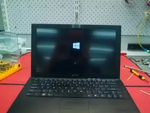
    • Success!

Conclusion

To reassemble your device, follow these instructions in reverse order.
zacxzac

Member since: 29/09/15

2011 Reputation

12 comments

Hi- How difficult is it to replace the lcd? can i just unclip the bezel or would i need to take it off the hinges and follow this guide?

MrTay -

I think you need to take the case off, then take the lcd off. I haven't done it on the z2, but I did do it on the z1.
zacxzac -

Thanks for the response, i cant for the life of me find a guide anywhere for the Z2. Was the bezel clipped on or glued on for the Z1?

MrTay -

any support would be hugely appreciated :)

MrTay -

Sorry to be pain, can i detach and re-attach the main motherboard cable for the right hinge without taking the motherboard off? Also are the there any cables from the left hinge i need to be aware of?

MrTay -

The Z2 was put together quite differently - a lot less room inside than the Z1. The screen on the Z1 was clipped on around the outside. Fairly intuitive to remove it as long as you go slow and be cautious.

It's be a while since I wrote this, but from memory the Z2's display should detach via plugs near the hinge-end of the motherboard. I wouldn't expect that you'll need to take the motherboard out.

The silver strip at the bottom of the LCD also covers some cables related to the antenna (which goes around the outside edge of the display.

Just a thought - if you do take yours apart, take some pictures and make a guide on ifixit. The Z2 was really well built, and it is great to be able to keep them serviceable.

zacxzac -

I performed all the operations and laptop works but it does not see the battery now. Any guesses where I could made a mistake (may be disconnect smth).

Kirill Lykov -

Hi- did you get to the bottom of the no battery detection issue? Im getting the same after taking the laptop apart

MrTay2 -

Quick update- ive managed to fix it (Opened it back up). Seems like i put too much pressure when screwing back the motherboard. Just had to loosen some screws.Hope this helps if you are still having issues.

MrTay2 -

Thank you very much. Great guide!

Miguel Lobo -

What is the thickness of the thermal pad on intel’s PCH (south bridge)? Is it 0.5 mm or more?

Krz Krz -

Very helpful. Great Article

Joe Fung -