
Introduction
This guide will show you how to disconnect and remove the main circuit board of the Alpha 65 camera. This requires using a Phillips #00 screwdriver, plastic opening tool, and tweezers. Be sure to keep track of all screws and parts removed from the camera.
-
-
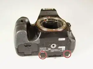
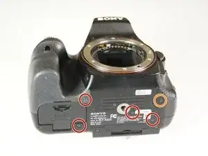
Remove the two 4.0 mm Phillips #00 screws on the base of the camera.
-
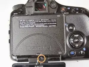
Remove the 3.0 mm Phillips #00 screw on the hinge of the screen.
-
-
-
Remove the two 2.0 mm Phillips #00 screws on the bottom-right side of the screen.
-
Remove the two 2.0 mm Phillips #00 screws on the bottom-left side of the screen.
-
-
-
Use a plastic opening tool to disconnect the silver wires from the screen's circuitry and completely remove the screen from the camera.
-
-
-
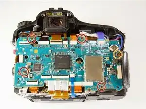
Unscrew the four 4.0 mm Phillips #00 screws with a on the base of the camera below the the scheme that separates the front and back panels.
-
Unscrew the 5.0 mm Phillips #00 screw on the bottom right of the camera.
-
-
-
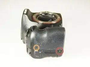
Unscrew the 4.0 mm Phillips #00 screw on bottom of the left side of the camera.
-
Unscrew the 5.0 mm Phillips #00 screw near the top of the left side of the camera.
-
-
-
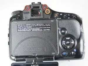
Unscrew the two 4.0 mm Phillips #00 screw at the top of the camera by the eyepiece.
-
Unscrew the 5.0 mm Phillips #00 screw of the dial below the other two screws.
-
Once all the screws are removed, carefully use your hands to detach the back panel from the camera. Working around the edges can help as well.
-
-
-
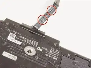
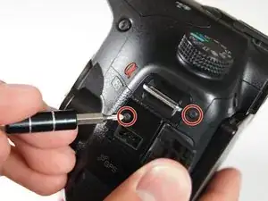
Remove the two 4.0 mm Phillips #00 screws on the right of the camera that are located on the upper right side and under the "Remote" port flap.
-
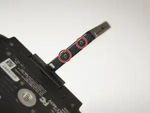
Detach the right side panel with the remote and HDMI ports of the camera by gently pulling on the panel.
-
-
-
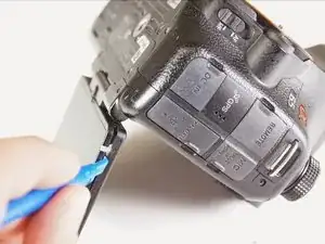
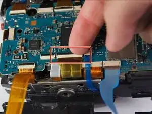
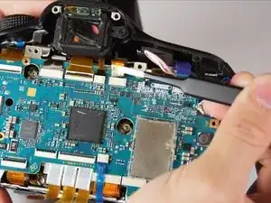
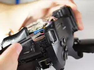
Use tweezers to remove the blue and orange ribbon connectors from their connection points pictured here.
-
-
-
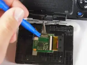
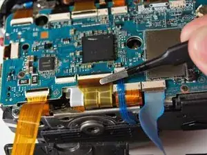
Use your finger to flip the switch that holds the dual ribbon connector in place.
-
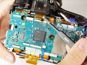
Gently use tweezers to disconnect the dual ribbon connector and the thin blue ribbon connector to the right of it from the circuit board.
-
-
-
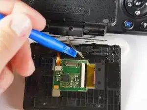
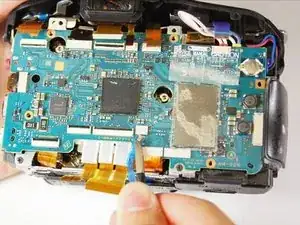
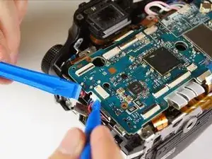
Use tweezers to disconnect the blue, gold, and brown ribbon connectors near the top of the camera.
-
-
-
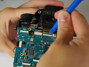
Use a plastic opening tool to pop open the connector holding the next ribbon to the circuit board.
-
Use tweezers to disconnect the ribbon.
-
-
-
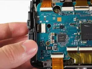
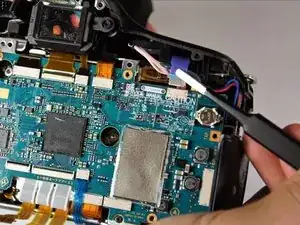
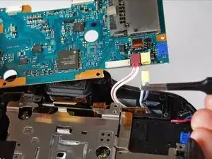
Use either plastic opening tools or tweezers to unplug the white adapter located on the right side of the circuit board.
-
-
-
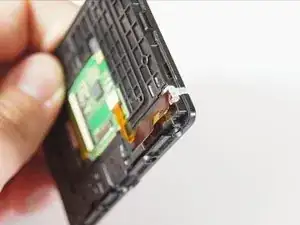
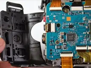
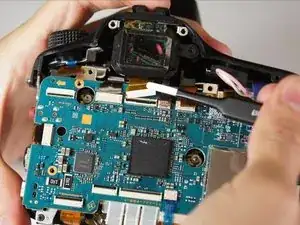
Gently lift the circuit board away from the camera and turn it over.
-
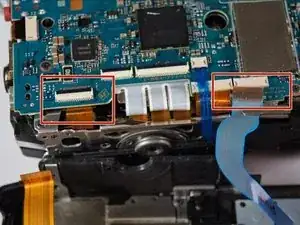
Use tweezers to disconnect the final two plugs and completely remove the circuit board from the camera.
-
To reassemble your device, follow these instructions in reverse order.
4 comments
I posted this link to a "Can't read SD card problem" below. On most SLTmodels apparently the SD card reader is part of the main circuit, and my local repair shop wanted $160 for labor (!) to swap out the part:
does anyone know if replacing the motherboard would fix a fried aperture lever control motor?
My camera will not read SD cards and intermittent struggles with lens connections. I sent it out for repair and the response was as follows: “AM main board would need to be replaced and is no longer available.” Is the AM main board another name for the Mother Board?