Introduction

The motherboard is the brains of the camera. Replacing the motherboard requires completely opening up the camera.

  1. UjA1uwhSbKedws4h
    • Open the battery compartment by sliding the lock to the right.

  2. kt1KOD3PI3UsBIGA
    • Push in the blue lever.

    • The battery is on a spring so make sure you have control over it, or it might fly out.

  3. E45ljNM5OiOnUD61
    E45ljNM5OiOnUD61
    tYZtYWBKOHekDb5K
    • Pull the battery out.

  4. kQJxeCQFOCZM1iqb
    kQJxeCQFOCZM1iqb
    2Bn31dfFa2PPokTR
    GCn2im1FhPdBrDkb
    • Make sure to turn the cameras power switch to off before beginning this step.

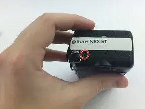
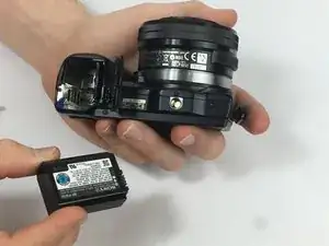
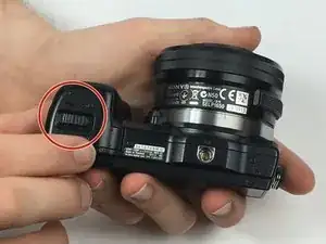
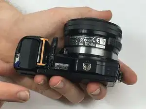
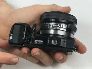
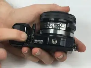
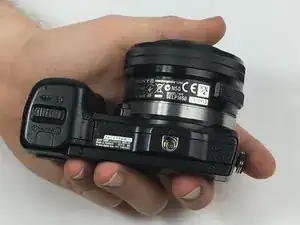
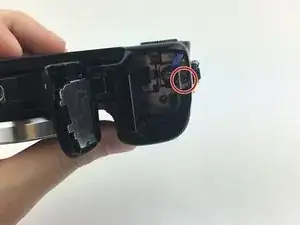
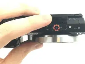
    • Begin by holding the camera upside down with the bottom facing you. Identify the housing for the SD card, and battery.

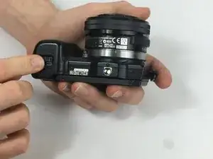
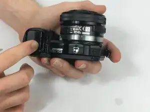
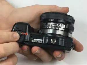
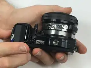
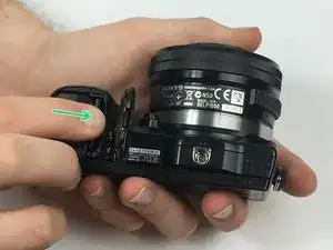
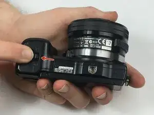
    • You will use your other hand to slide the lock switch to this housing to the right. This will release the cap, allow it to come upwards.

  5. 3ENSmLAnFkkJM4lv
    3ENSmLAnFkkJM4lv
    y4HjCHkeOTTDBBYm
    pNXOwXPkZfYtXU5d
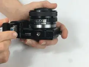
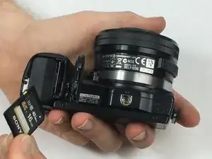
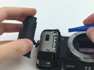
    • Now that the cap to the battery and SD card housing is open, the SD card is visible.

    • You will need to press down on the SD card until you hear a click. Release the SD card and it will now be available to remove.

    • Grip the SD card and pull it out of the SD card slot.

  6. QMd3IQtYBDKNqcBx
    QMd3IQtYBDKNqcBx
    IVenjPJDOEYLAOKy
    nsZIDZEF13YBXmXr
    • To reinsert the SD card place it in its housing.

    • You will then need to push down on the SD card until you hear a click.

    • To ensure the SD card is in place you can visually inspect it. The SD card should be flush with the housing.

  7. BWRSIWx41UTGgFtV
    BWRSIWx41UTGgFtV
    2WUC4unLVf6ndyWR
    EOuWYlIaQmRcDJxk
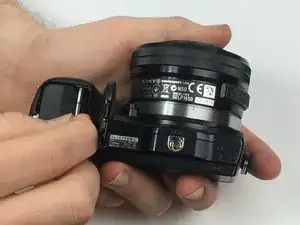
    • You may now close the housing for the SD card and battery.

    • Close the cap and while holding it down slide the locking tab to the left. This step should lock the cap in place.

    • Your SD card is now safely in place and you may turn your device on.

  8. PfAGAMSGqqpb4NSW
    • Remove the 3.5 mm exterior-side screw.

  9. 3A51InvBumKKIBYi
    • Remove the 3.5 mm bottom screw from the battery compartment.

  10. 45sffb1NgoxMmYJS
    • Pry off the front-side cover with the small plastic spudger.

    • There is a adhesive holding the front-side cover to the camera frame, so more force may be necessary to remove it. Be careful as to not break the cover while prying.

  11. VHMPwDKKGQgwvutI
    • Remove the 3.5 mm bottom screws.

  12. pIqXCWDKCLLTdCcO
    pIqXCWDKCLLTdCcO
    Lp2yTMpMBO2ctWGe
    • Open the USB cover on the side of the camera.

    • Remove the 3.5 mm USB side screws.

  13. KDZjCRKxUT5fqeTv
    • Remove the 4mm screws at the back of the battery compartment.

  14. ux4AyH2BPjGlPgoe
    • Remove the 3.5 mm top flash-mount screw.

  15. TGkIS1IFDFkll6TJ
    • Flip the screen up.

    • Pry the top cover off with the small plastic spudger.

  16. toSe4bX2hV5Xpfjr
    toSe4bX2hV5Xpfjr
    vPAZ3rWKTHIiet6M
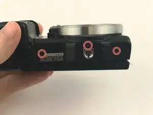
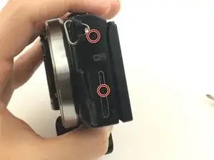
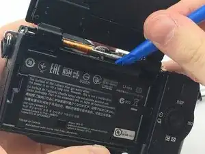
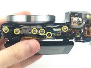
    • Pry the top part rear cover off with plastic spudger.

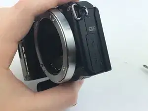
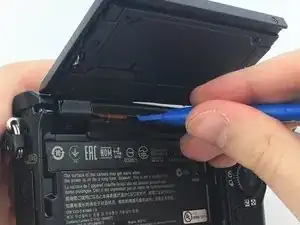
    • Flip the camera so the sensor faces down and push up on the rear cover from the battery compartment.

  17. JpHJxwkfNGqOaS1x
    • Remove the 2.25 mm tripod mount screws.

  18. lnKiacOiWrcyLf5U
    lnKiacOiWrcyLf5U
    GMtGoodQe6hTKVGo
    • Remove the 2.25 mm side lanyard mount screw.

    • Pull the lanyard mount to remove.

  19. IWeNKhbUTdTrWFyE
    • Remove the 2.25 mm screws from the top.

  20. L3qIPpuasKPwqwZE
    • Using the tweezers, pull out the rubber grommet.

    • There is nothing holding the grommet in other than friction.

    • The grommet is small, don't lose it.

  21. 21PRDvHPvUDJZqsu
    • Pull the lead that was under the grommet out from the frame.

  22. aJffROmlsGJrlEyB
    aJffROmlsGJrlEyB
    D2lCDQGn4xZhWuol
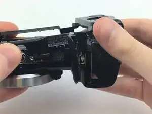
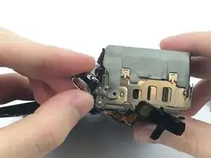
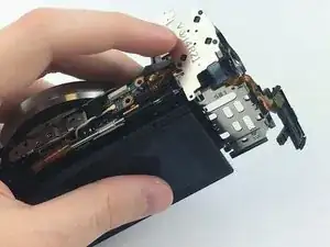
    • Flip the rotary selector and controls up over the top.

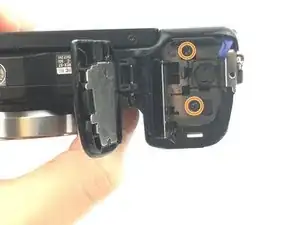
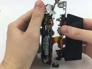
    • Holding the controls in place, pull the two frame pieces apart.

    • There is a connection between the motherboard and the LCD screen still attached to both halves, so don't pull to hard.

  23. T4Dsywxofr5GsZZM
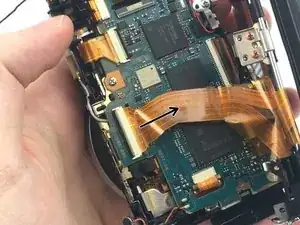
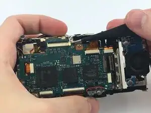
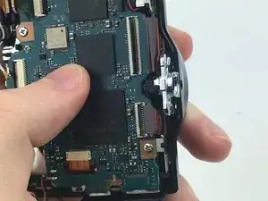
    • Disconnect the connection between the motherboard and LCD screen by pulling out the connector in the direction of the arrow.

  24. CpAdxZZiwvOufJmm
    CpAdxZZiwvOufJmm
    fgbndIUQKlBOPVJh
    • Using the tweezers, disconnect the metal lead at the top of the motherboard by pulling up.

  25. rRoG3tcIv5tlfMdb
    rRoG3tcIv5tlfMdb
    FcXZFIKcTSpPILbP
    12HC4WDywNEoSy1A
    • Disconnect the two top-right connectors by pulling them up towards the top.

  26. O13ug3RHKdrwAw2Q
    O13ug3RHKdrwAw2Q
    tsVfQEvyN3kuv3UX
    • Disconnect the two connectors on the right by pulling them to the right.

  27. KATPxFjBYFgkF4RC
    KATPxFjBYFgkF4RC
    4fOhplWZSr2ZHJUp
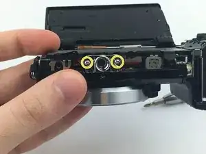
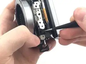
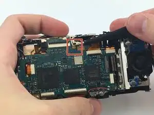
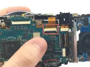
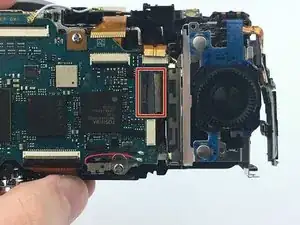
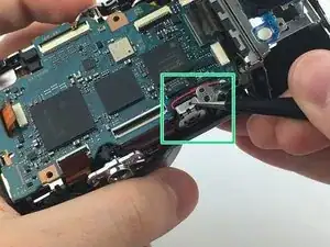
    • Using the tweezers, flip open the black door on the large connector on the bottom.

    • Remove the connector by pulling it away from the motherboard.

  28. uHmRacBHT5TZtZvU
    uHmRacBHT5TZtZvU
    dpikHeMu3yjcY3kN
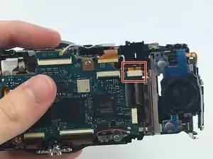
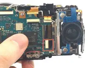
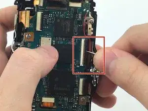
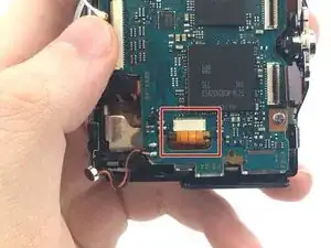
    • Using the tweezers, flip open the door on the smaller connector.

    • Remove the connector by pulling it away from the motherboard.

    • This is the same process for from the previous step.

  29. ed1cBgDAkBebBWXf
    ed1cBgDAkBebBWXf
    D3r2doZJB6qmhhTM
    • Disconnect the connector that goes through the motherboard.

    • There is no door on this connector.

  30. 2ZUdACENDYJbSMZd
    • Remove the 4 mm screws securing the motherboard to the frame.

  31. kKDDMgDNr2wSVsG5
    kKDDMgDNr2wSVsG5
    IrZ1rSwcFf3VcIov
    • With the tweezers, remove the metal speaker cover.

    • Pull the speaker out of the frame.

    • Remember how the wires lay back in the frame for reassembly.

  32. XGbX3i4FquPAD1Dg
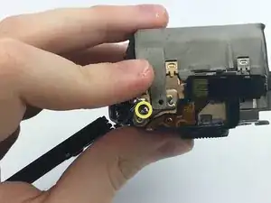
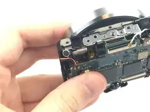
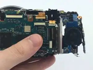
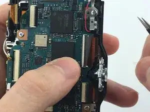
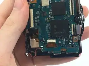
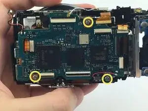
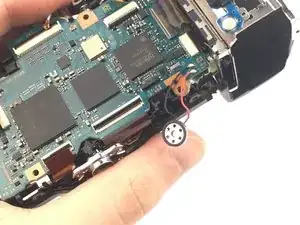
    • Flip the motherboard up and disconnect the connector on the back.

    • Seperate the motherboard from the frame.

Conclusion

To reassemble your device, follow these instructions in reverse order.

William Kleinman

Member since: 02/03/17

301 Reputation

0 comments