Introduction

  1. 5Y2QBubgjuqieDOS
    5Y2QBubgjuqieDOS
    qTpVcVUWgSBPMY3X
    NdoNDZiXf6Ca3AMy
    • Remove battery by sliding the tab to open the cover

  2. Z3KEOwyuBVtSEtx6
    Z3KEOwyuBVtSEtx6
    vMvnSSMe5R5kUY3M
    MlnwUdLYcgHPyeGb
    • Using the screwdriver, remove all screws (black 2.5mm) from outermost layer of the assembly.

    • All screws in the camera can be removed with the PH 0 driver head.

    Split this step up into multiple steps based on where screws are being removed from or specify how many screws are removed in this step

    Alberto Rodriguez -

  3. GG2aQQtS1CsNUUhJ
    GG2aQQtS1CsNUUhJ
    IwUu5k2QkIRbVrCy
    3yZCDQOcYkUHrBLs
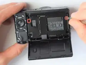
    • Also using the screwdriver, remove screws (black 1mm) underneath articulated LCD screen.

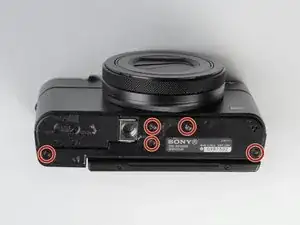
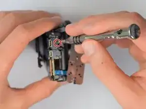
    • Remove the marked 2.5 mm screws with the screwdriver

    2 different types of screws are removed in this step: specify the types

    Alberto Rodriguez -

    It is not necessary to remove the hinge screws. It is much easier to remove the back panel with the LCD still attached and not flopping about everywhere.

    cheez -

  4. Xr6yoceDwVfYLRHB
    Xr6yoceDwVfYLRHB
    GniLMdDCx3nG4ohr
    • Using the plastic opening tools, carefully pry off the bottom plate.

    • Do not pull too hard as you may break the plastic casing.

  5. JU6eJ5bmNvjDbREs
    JU6eJ5bmNvjDbREs
    VWIhdEEYGZMxWIxe
    16QlMwHqRJSrm6xt
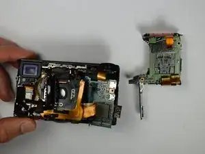
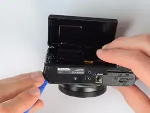
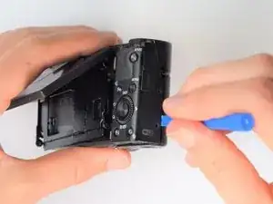
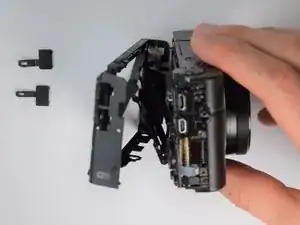
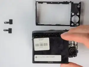
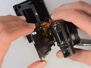
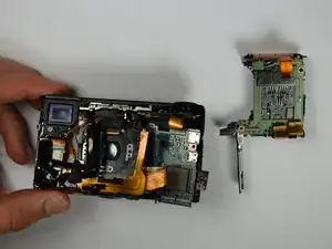
    • Using the same plastic opening tools, separate the screen and back assembly from the front portion of the camera

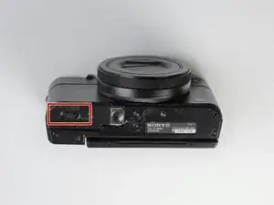
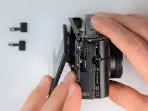
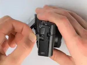
    • Once the back assembly is slightly detached, pull the media covers for the HDMI and Multimedia ports

  6. XEbRkOZPBxegUcI5
    XEbRkOZPBxegUcI5
    YxBiZDRVQfEZAWue
    • Remove the back cover

  7. R4bXWIwmhBJgMINV
    R4bXWIwmhBJgMINV
    ngWyBMQRcC14gTJE
    FGnWSQGTtR2LEmx6
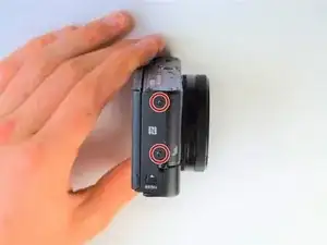
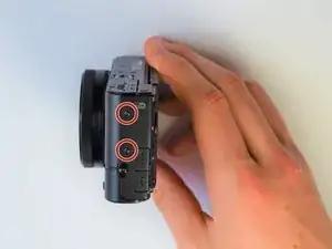
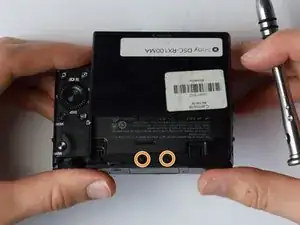
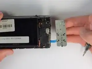
    • Move side panel to get access to screws

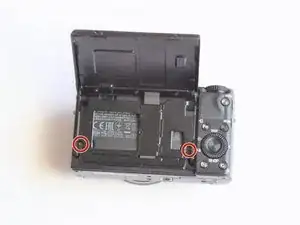
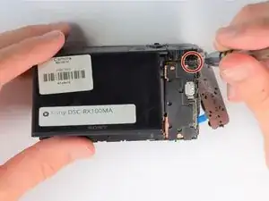
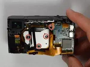
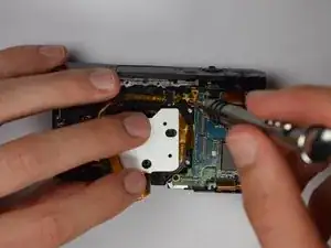
    • Remove two screws (black 2.5mm) with PH #0 screwdriver

    In the second picture of the side, it is not the upper screw by the USB that needs removing, but the lower one by the SD/battery door

    James Robinson -

  8. 6UMcTZqlJBVbAXAx
    6UMcTZqlJBVbAXAx
    jykx1qJPqRsSoEUt
    • Remove back panel assembly while still keeping ribbon cable attached

    • Be very gentle and care not to tear the gold ribbon cable. This will be a common theme throughout these replacement guides.

  9. HmdEQsABVKCQx5HE
    HmdEQsABVKCQx5HE
    lTOnRX1jBGnwPAM3
    • Carefully unplug ribbon connector to fully detach LCD screen assembly from camera

    It is worth saying that the grey line on the left-hand edge of the flex connector flips up to release the flex.

    And Rew -

  10. PjmAwNAG1xByjwWQ
    PjmAwNAG1xByjwWQ
    pcOdRLlYU4C4Byov
    • Remove remaining screw which holds the copper casing in the camera

    this is the HDMI cover

    James Robinson -

  11. S4GI26YYVQQrCrJd
    S4GI26YYVQQrCrJd
    mUSyBTjDZbMk2GZ1
    UmoFmIX2w1TkXMuA
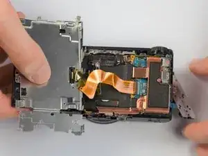
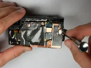
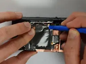
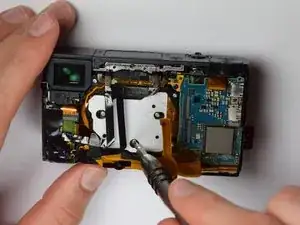
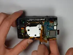
    • Using the plastic opening tools, carefully pry off the copper casing at the two pictured points.
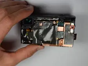
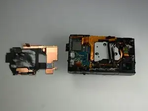
    • Remove casing

    I still have two black glued maybe cables above the copper board. Can't find them in the description but they are already missing in your picture of step 10.

    Simon -

    The connector next to the display connector is unplugged in the last picture of step 11 but not mentioned in the text.

    Simon -

  12. B6XWEHFHjTs6Sp3T
    B6XWEHFHjTs6Sp3T
    TZEfJTL2jctbLfbe
    uPx1SZB1SRoKTJwj
    • Using Philips Screwdriver, remove the four screws as marked on the picture

  13. WRfg3xZ6AWQgRYlf
    WRfg3xZ6AWQgRYlf
    M6edGyMvEsi6q3Bp
    UG6SYyBQE3LrGmCy
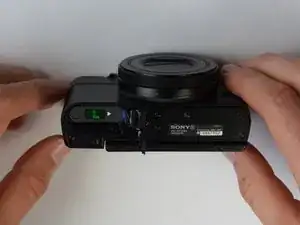
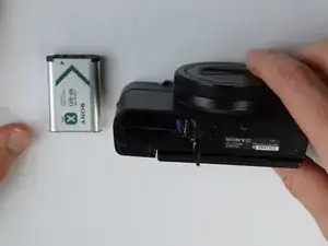
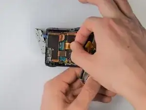
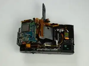
    • Place your finger into the battery port and push up on the SD card holder to push it out of its socket.

    • Give it a little wiggle and you should feel the SD card holder come out.

    Warning Take care because at this stage the senor chip will become exposed to contamination. the grey plate is its heatsink.

    Mal Beckford -

    The small cover of the HDMI port was removed here as well.

    Simon -

  14. JPTKSBBOsoheHPFR
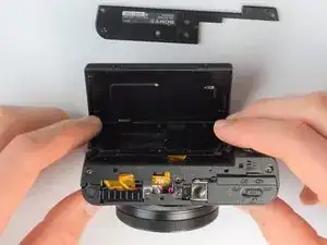
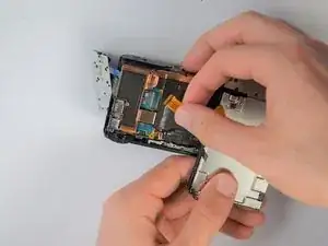
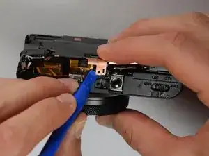
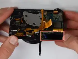
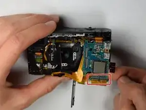
    • Carefully remove the gold ribbons from the ports of the motherboard by lifting the gray tabs and pulling away the ribbon

    • You may want to use tweezers to remove the gold ribbons as a more delicate and safe approach, but this is not required

    • Do not pull away motherboard too hard as the ribbons are very fragile

  15. FOAowNAq5iMWCRoh
    • Remove the SD card holder. It should easily come out because all of the prerequisite screws were already removed.

Conclusion

To reassemble your device, follow these instructions in reverse order.

Isaiah De Leon

Member since: 30/01/17

418 Reputation

One comment

Dear Isaiah De Leon !

I have a Sony RX 100 Mk4, and it is out of order.  :(

First just the digital zoom button (up on the camera) didn't work

Later the manual zoom (lens ring moving) didn't work

Now the rest of the marked buttons does not work.

(Sometimes yes, but usually no funcion at all)

The camera was handled care, didn't fall down, no water contact!

Sony service says, no physical problem, they advise the panel to be replaced. (It is about 120€ + 60€ working fee)

Some Sony fan member advised “the little cable just under dial there that connects all the controls has slowly slipped out. “ could be the problem,

Could You please send a picture which cable can it be, or please any other advice.

Thanks!!!

Ádám

berkesi.adam@gmail.com

adama1492 -