Introduction

  1. 5Y2QBubgjuqieDOS
    5Y2QBubgjuqieDOS
    qTpVcVUWgSBPMY3X
    NdoNDZiXf6Ca3AMy
    • Remove battery by sliding the tab to open the cover

  2. Z3KEOwyuBVtSEtx6
    Z3KEOwyuBVtSEtx6
    vMvnSSMe5R5kUY3M
    MlnwUdLYcgHPyeGb
    • Using the screwdriver, remove all screws (black 2.5mm) from outermost layer of the assembly.

    • All screws in the camera can be removed with the PH 0 driver head.

    Split this step up into multiple steps based on where screws are being removed from or specify how many screws are removed in this step

    Alberto Rodriguez -

  3. GG2aQQtS1CsNUUhJ
    GG2aQQtS1CsNUUhJ
    IwUu5k2QkIRbVrCy
    3yZCDQOcYkUHrBLs
    • Also using the screwdriver, remove screws (black 1mm) underneath articulated LCD screen.

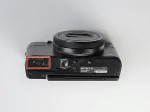
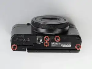
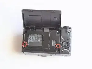
    • Remove the marked 2.5 mm screws with the screwdriver

    2 different types of screws are removed in this step: specify the types

    Alberto Rodriguez -

    It is not necessary to remove the hinge screws. It is much easier to remove the back panel with the LCD still attached and not flopping about everywhere.

    cheez -

  4. Xr6yoceDwVfYLRHB
    Xr6yoceDwVfYLRHB
    GniLMdDCx3nG4ohr
    • Using the plastic opening tools, carefully pry off the bottom plate.

    • Do not pull too hard as you may break the plastic casing.

  5. JU6eJ5bmNvjDbREs
    JU6eJ5bmNvjDbREs
    VWIhdEEYGZMxWIxe
    16QlMwHqRJSrm6xt
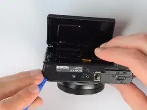
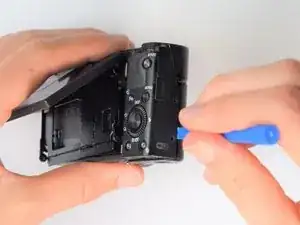
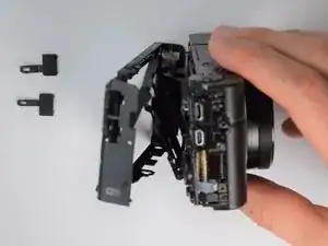
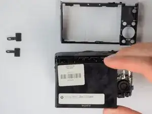
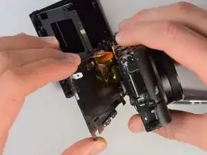
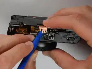
    • Using the same plastic opening tools, separate the screen and back assembly from the front portion of the camera

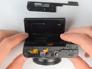
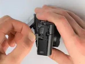
    • Once the back assembly is slightly detached, pull the media covers for the HDMI and Multimedia ports

  6. XEbRkOZPBxegUcI5
    XEbRkOZPBxegUcI5
    YxBiZDRVQfEZAWue
    • Remove the back cover

  7. R4bXWIwmhBJgMINV
    R4bXWIwmhBJgMINV
    ngWyBMQRcC14gTJE
    FGnWSQGTtR2LEmx6
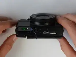
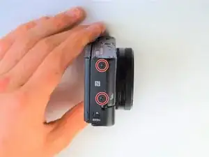
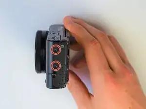
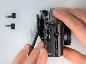
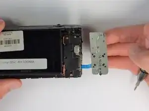
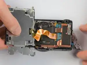
    • Move side panel to get access to screws

    • Remove two screws (black 2.5mm) with PH #0 screwdriver

    In the second picture of the side, it is not the upper screw by the USB that needs removing, but the lower one by the SD/battery door

    James Robinson -

  8. 6UMcTZqlJBVbAXAx
    6UMcTZqlJBVbAXAx
    jykx1qJPqRsSoEUt
    • Remove back panel assembly while still keeping ribbon cable attached

    • Be very gentle and care not to tear the gold ribbon cable. This will be a common theme throughout these replacement guides.

  9. HmdEQsABVKCQx5HE
    HmdEQsABVKCQx5HE
    lTOnRX1jBGnwPAM3
    • Carefully unplug ribbon connector to fully detach LCD screen assembly from camera

    It is worth saying that the grey line on the left-hand edge of the flex connector flips up to release the flex.

    And Rew -

  10. wUQNGqkoZwAt1JXp
    wUQNGqkoZwAt1JXp
    lPY6RdE2TIqcyyM2
    • Using the Philips Screwdriver, remove the screw (black 3mm) located on the copper casing.

  11. NFOEskWA1qYCSt4R
    NFOEskWA1qYCSt4R
    BCSgIXDPi5J6xYdn
    PSLJqENZqRAeBwiW
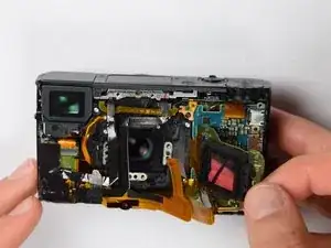
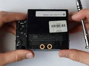
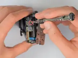
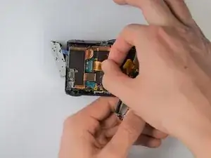
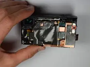
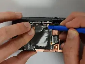
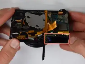
    • Using the plastic opening tools, carefully pry off the copper casing at the two pictured points.
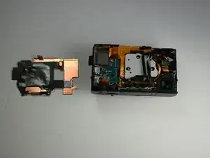
    • Remove casing.

  12. tf3fbZDCrZtGaZXL
    tf3fbZDCrZtGaZXL
    myq6LdcRrsnWwWNZ
    CbO4pkSZs1xINciN
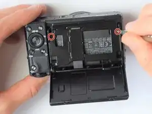
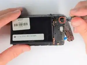
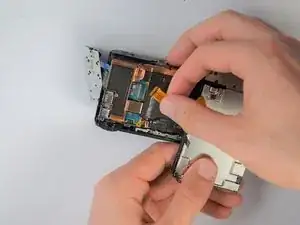
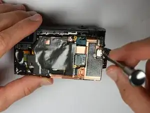
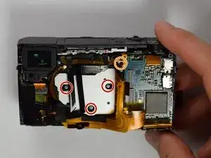
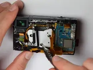
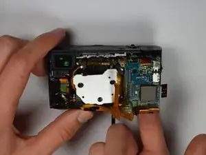
    • Using the Philips screwdriver, remove the three (silver 3mm) screws

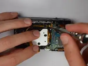
    • Remove the screw (silver 2mm) from the upper right hand corner

  13. 4vEliakfqNUTDFyM
    4vEliakfqNUTDFyM
    JmpOGYWLX1bAhcjt
    NtOBvoJSHI3JMEKU
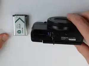
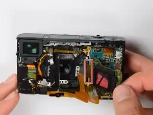
    • Place your finger into the battery port and push up on the SD card holder to push it out of its socket.

    • Give it a little wiggle and you should feel the SD card holder come out.

  14. hSZu3EY6BTHMrdpd
    • Now you can remove the marked gold ribbon cable from the SD card holder.

    • Utilize extreme caution while removing because the ribbon cables are extremely fragile and important to the camera.

Conclusion

To reassemble your device, follow these instructions in reverse order.

Isaiah De Leon

Member since: 30/01/17

418 Reputation

0 comments