Introduction
The motherboard is one of the hardest components on the camera to replace. Be very careful when taking apart the ribbons, you could accidentally damage other parts of the camera.
-
-
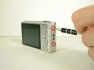
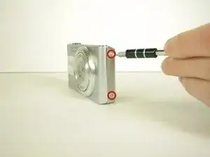
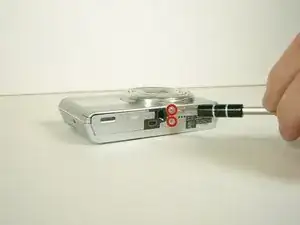
Open the battery/memory card door and remove the 6 screws (.35cm) with a Philips 000 screwdriver. There will be two screws on the left and right sides, and two on the bottom.
-
-
-
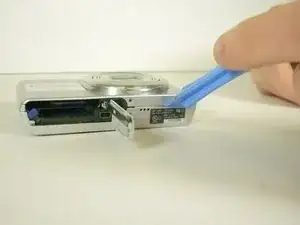
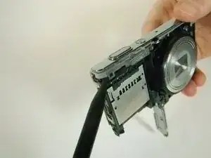
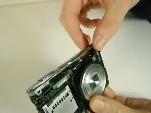
Unscrew the .45cm screw located on the upper right corner on the back of the camera. Once the screw is off, use the spudger and unclip the piece holding the top down on the upper left on the front of the camera. It should lift off with ease.
-
-
-
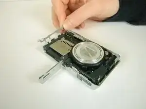
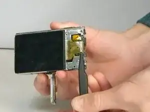
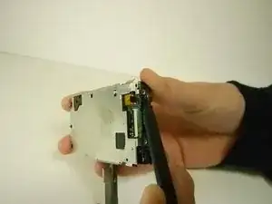
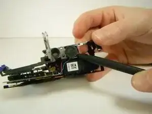
Flip over the control board then use tweezers to pull out the ribbon connecting the circuit board to the motherboard.
-
-
-
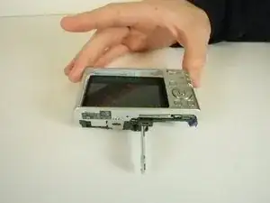
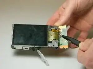
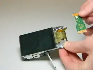
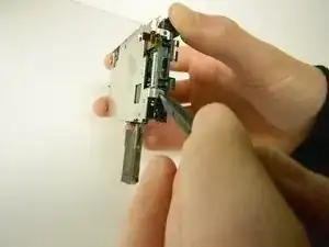
Use tweezers to remove the ribbon that is connected from the LCD screen to the camera by pulling the part that is folded under, out.
-
-
-
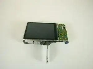
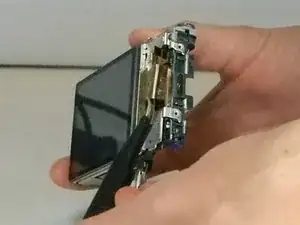
Slide the right side of the LCD screen clockwise, which will push it off the camera. The rest of the screen should come off with it with ease.
-
-
-
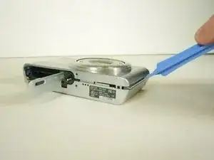
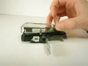
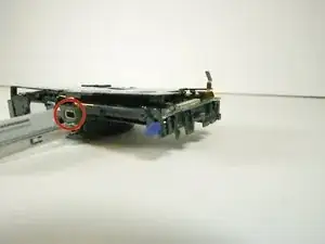
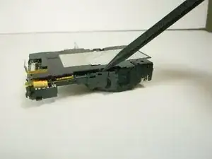
Use the spudger and disengage the black plastic clip located on the bottom right of the camera facing the lens.
-
-
-
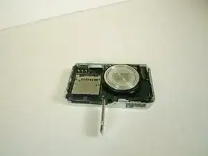
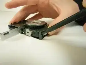
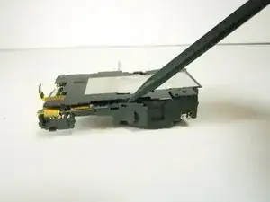
Flip the camera over, facing the bottom of the camera towards you. Then use the spudger to detach the plastic clip on the right, near where the LCD control board was.
-
-
-
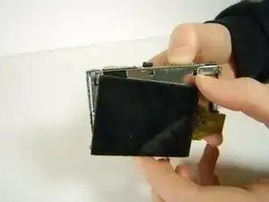
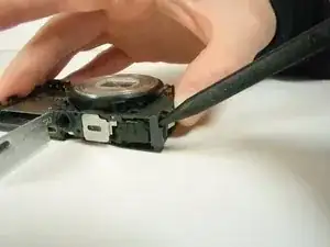
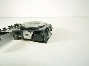
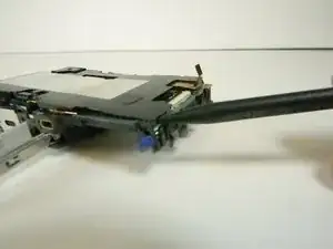
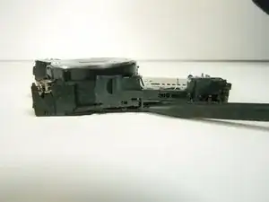
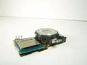
Use the spudger and seperate each end of the metal piece. Once the speaker is free you can lift off the plastic frame.
-
-
-
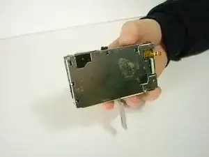
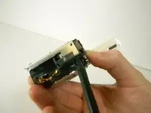
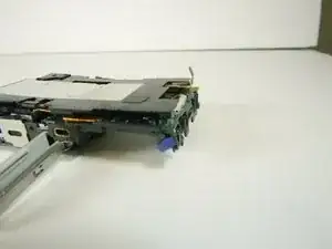
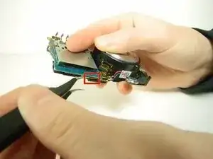
Use tweezers to disconnect the ribbon located under the motherboard near the bottom of the camera.
-
-
-
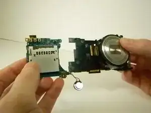
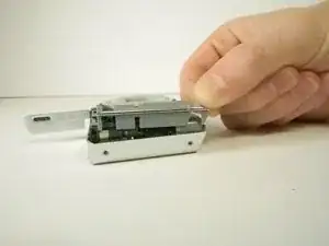
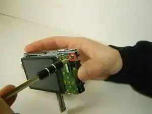
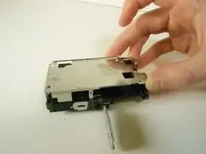
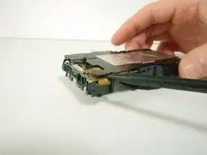
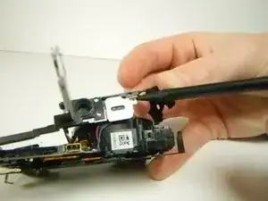
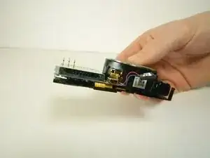
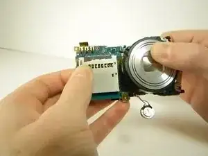
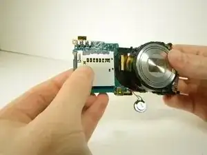
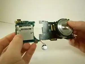
Now with one hand located on the plastic skeleton and the other on the motherboard pull the motherboard to the left to disconnect the last ribbon.
-
To reassemble your device, follow these instructions in reverse order.