Introduction

This repair guide will number and display the steps to remove the Motherboard for replacement.

  1. OeOXUuegDnlpQYYU
    OeOXUuegDnlpQYYU
    K2QmUID6hZhmvwNn
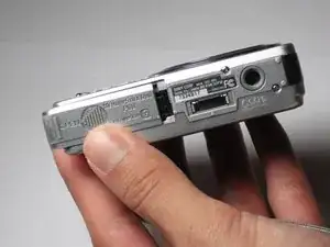
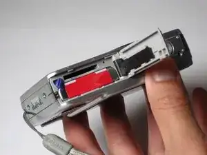
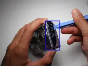
    • Slide the battery cover in the direction the arrow points.

    • Pull the battery cover towards you.

  2. YPALxLt51biBUMaF
    YPALxLt51biBUMaF
    v2ljpSKiXXTqWEGp
    • Flick the blue switch for the battery to pop out.

    • Remove the battery from the camera.

  3. yZbsrf1Vw1pAcYqk
    yZbsrf1Vw1pAcYqk
    4VZJi3tjuPJwrRKR
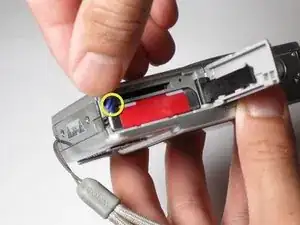
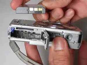
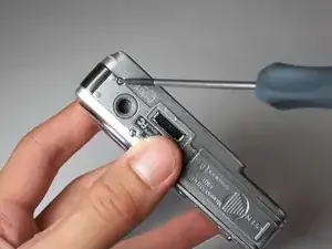
    • Using the Phillips #00 Screwdriver, remove the two screws from the caution panel.

    • Remove that panel.

    • Careful for falling pieces.

  4. vVEOf2H1HepRjSuM
    vVEOf2H1HepRjSuM
    wdVAJgbiKpfNEmff
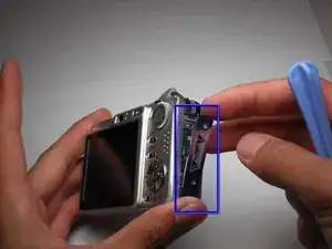
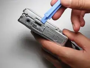
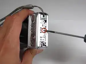
    • Remove the screw with a Phillips #00 screwdriver from the right side of the camera (with '3x optical zoom' engraved on the side panel).

    • Remove that panel.

  5. Yy6mpUjcegpkjWSJ
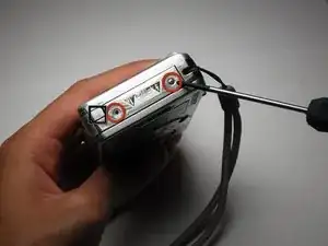
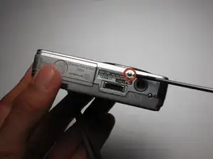
    • Remove the screw using the Phillips #00 screwdriver from the bottom of the camera, closest to the back cover.

  6. GYSnrO3p2jHl2fHG
    GYSnrO3p2jHl2fHG
    C4TE6oIpiylqmqPO
    • Gently remove the back cover.

    • It may be a bit stiff, so use some force to remove it. Proceed with caution.

    Muchas gracias, muy claro!!

    Ruben -

  7. qO4YkrLYebcaKbJk
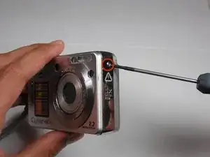
    • Remove the screw using a Phillips #00 screwdriver on the left side (where the "3x optical zoom" panel use to be).

  8. rloynaonOrY5MZCq
    rloynaonOrY5MZCq
    GArHOYsPH6QZujSr
    HMAYoX3eXbyToZTg
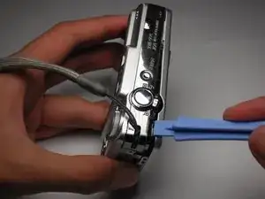
    • Remove the small screw using a Phillips #00 screwdriver on the bottom of the camera attached to the front cover.

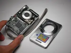
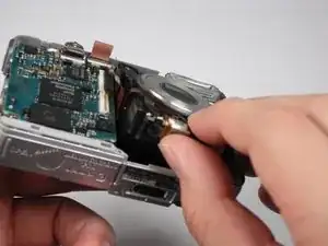
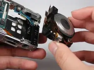
    • Gently remove the front cover.

    • Put a little force to pop off the case. Proceed with caution.

  9. HysxnjhHqTQPd5Wr
    HysxnjhHqTQPd5Wr
    JdrmKsRKNV4qoeqO
    • Flip the black secure locks off. Tweezers may be necessary.

    • Detach the two orange cables.

  10. F3YDfsOAUjxVlUSL
    F3YDfsOAUjxVlUSL
    kvUDFKpCcRXjkfAv
    • Gently pull the lens container out of the camera.

  11. CsqFpFPldO6qvUZJ
    • Remove the black screw using a Phillips #00 Screwdriver on the motherboard.

  12. fBoAPY1a6TPMNtfD
    fBoAPY1a6TPMNtfD
    mgrsdGHyZfd3N2ex
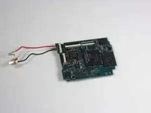
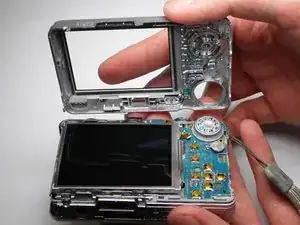
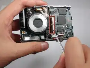
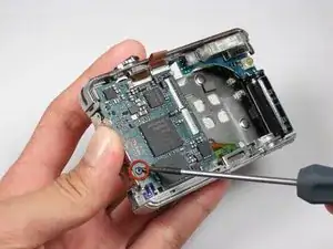
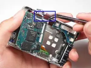
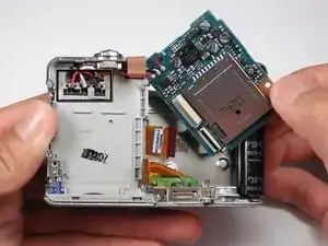
    • Remove the two orange cables on the top of the motherboard with tweezers.

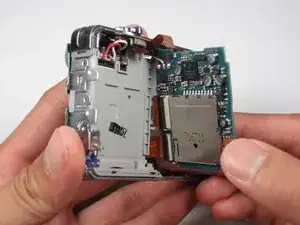
    • Lift the motherboard out of its slot.

  13. KGhYSUY2hFJHptDS
    KGhYSUY2hFJHptDS
    CJnDtMyOyqpdyVHn
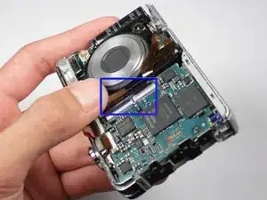
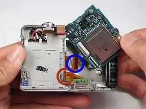
    • For the AV port, detach the bottom orange cable.

    • For the LCD screen, detach the top orange cable on the right side of the motherboard.

    • For the motherboard, detach all the orange cables.

    • Careful not to damage the red, white, and black wires when lifting the board.

Conclusion

To reassemble your device, follow these instructions in reverse order.

Christopher Wakamatsu

Member since: 11/10/10

111 Reputation

0 comments