Introduction

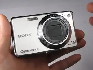
Make sure you have all of the requisite tools on hand before beginning to replace the flash bulb.

  1. bbVZZyic1JVdYeQT
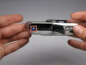
    • Find the hatch labeled "open" on the left side of the bottom of the camera.

    • Slide the hatch in the direction that the arrow is pointing. The hatch will open outward on its own.

  2. ditCHfiS46xgZkRv
    • Slide the blue locking tab to release the battery.

    • Slide the battery out of the camera.

  3. FCFVPb5u1WysqYRF
    FCFVPb5u1WysqYRF
    6MGRACEbXrLcoGga
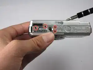
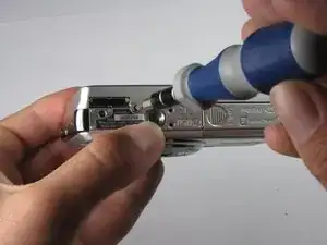
    • Replace hatch and rotate camera 180 degrees. You should still be looking at the bottom of the camera.

    • Remove the four 2.5mm Phillips #0 screws.

  4. TOjP3eXT4jbYCKXX
    TOjP3eXT4jbYCKXX
    iGw4XYLFcJPRQUWh
    sovRbUMSZm1se2GU
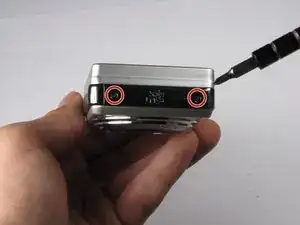
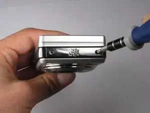
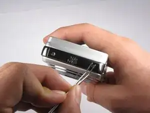
    • Turn the camera so the left side-panel reading "5x Optical Zoom" faces you.

    • Remove the two 2.5mm Phillips #0 screws.

    • You may have to remove the screws with a pair of tweezers when the screws are almost out.

  5. vPGjomWdyRANSuyj
    vPGjomWdyRANSuyj
    gUc34dWaSMQabLLN
    4vBrssYEFDoaYl4e
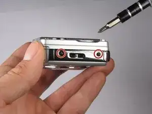
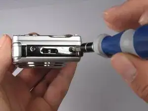
    • Turn the camera so the right side faces you.

    • Remove the two 2.5mm Phillips #0 screws.

    • You may have to remove the screws with a pair of tweezers when the screws are almost out.

  6. vmWbwlryVU4VxTHQ
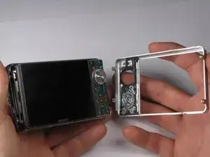
    • Rotate camera so that the back is facing you.

    • Pull the back casing directly away from the LCD screen.

  7. gBTRIsEJrivv3Owm
    gBTRIsEJrivv3Owm
    pscEhTFW2IHRx5TJ
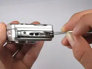
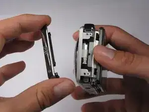
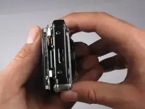
    • Turn the camera so that the left side is facing you.

    • Pull the left side-panel off of the camera.

  8. 2DYfmwLRrCIhFdVZ
    2DYfmwLRrCIhFdVZ
    VHdZaTtxgeOPnGC5
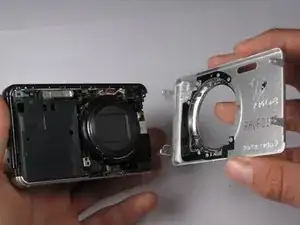
    • Turn camera so that the front of the camera is facing you.

    • Pull the front casing directly away from the camera.

    • The right side panel may fall off when you take the front panel off.

  9. 1RIsOX1QVTBCKGdl
    1RIsOX1QVTBCKGdl
    QX5q1DkBLDsHMfPp
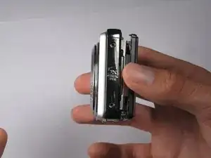
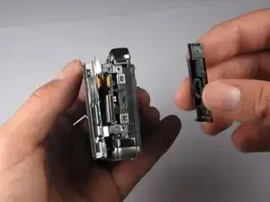
    • Turn the camera so that the right side is facing you.

    • Pull the right side-panel away from the rest of the camera.

  10. QI42XadwFLY2StFD
    QI42XadwFLY2StFD
    RgqrJm5KPevwasoy
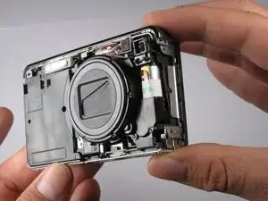
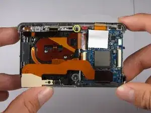
    • This is what your camera should look like now that you have removed the casing from all sides.

  11. TiqVqWWliRNhKBhG
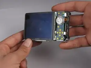
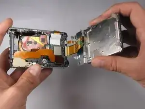
    • Gently pull the LCD and its casing away from the motherboard as shown.

    • Be careful not to rip out any ribbon cables.

  12. PFD4XTmTnCYFK6Hw
    PFD4XTmTnCYFK6Hw
    qtcNmNHwZOMMsTZL
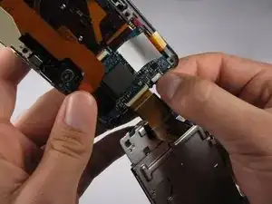
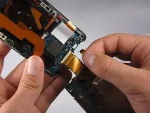
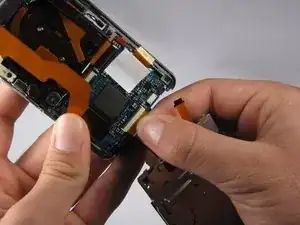
    • Disconnect the small ribbon-wire by gently pulling on the small ribbon-wire where it connects with the motherboard.

    • Do not use excessive force to remove the wire because this may cause it to tear.

    Caution: Do NOT attempt to remove the logic board itself until the LCD is completely off.

    Sanat Sahasrabudhe -

  13. fr3RlTjLvZDZxpJP
    fr3RlTjLvZDZxpJP
    wIPjdOYaXoNthVq4
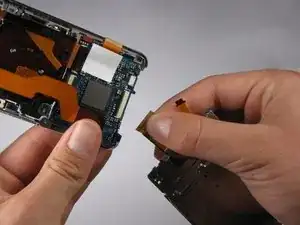
    • Disconnect the large ribbon-wire by pulling on the large ribbon-wire where it connects to the motherboard.

  14. SGIpIEvR1SArCww4
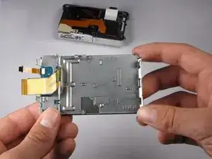
    • Pull the LCD and its casing away from the rest of the camera.

  15. JeODJgMXsSNZNBpe
    JeODJgMXsSNZNBpe
    G1AMcLSYRqPcucFW
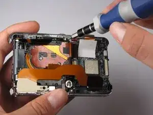
    • Turn the camera so the back is facing you.

    • Remove the 2.5mm Philips #0 screw at the top of the camera.

  16. kMaY5aYKMVRMtdP3
    kMaY5aYKMVRMtdP3
    HwdNRpgFPYNZl2nf
    cFwNRrWPngwvIabM
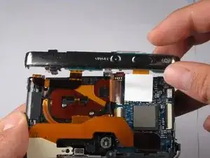
    • Tilt top casing up and towards you.

    • Carefully remove the right ribbon-wire from the top camera panel by pulling where the wire connects to the top.

    • Make sure to hold the camera with your thumb on the white square to ensure the ribbon-wire is not disconnected from the motherboard.

    • Carefully remove the left ribbon-wire from the top camera panel by pulling where the wire connects to the top.

  17. JKiH2LXDw4DM3jxW
    JKiH2LXDw4DM3jxW
    5nAXv1h1VLav1Ese
    KbJsOnuRGUTQVjKm
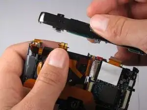
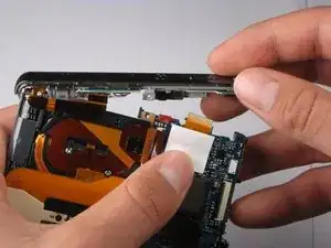
    • Pull the top of the camera off and turn it so the bottom is facing you.

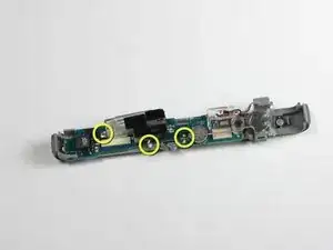
    • Desolder the three connections from the bulb to the small circuit board.

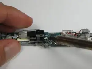
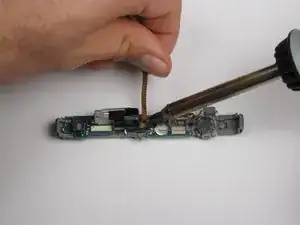
    • Remove the excess solder using your soldering iron and desoldering wick.

  18. noWpN1H14OSOymV1
    noWpN1H14OSOymV1
    ebvY6saUWSHFd5nZ
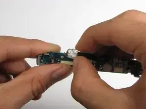
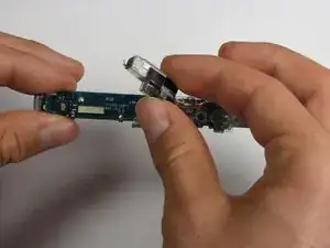
    • Gently wiggle the flash bulb to remove it from the joints.

    • It may be necessary to use the soldering iron to heat up the joints as you pull it off.

Conclusion

To reassemble your device, follow these instructions in reverse order.

William Schill

Member since: 04/10/10

222 Reputation

0 comments