Introduction

This guide will allow the user to access the motherboard for installation, replacement, or removal.

  1. rTcgis2rA2FBYUK4
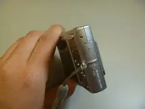
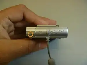
    • The battery cover is located on the right side of the camera.

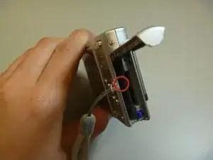
    • Slide the cover to expose the battery.

  2. mIV4RPQ3BEHBnTZl
    • Ensure that the battery lines up properly with the slot in the camera.

    • Slide battery in.

    • Slide cover closed.

    • Battery not shown

  3. OPlkYCl2krD4i62a
    OPlkYCl2krD4i62a
    DEcgngIMnvjrWmNc
    tjbljSTTy2oMGUpD
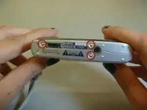
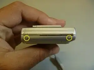
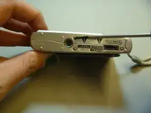
    • Remove screws from outside of camera. There are 6 screws total.

    • 3 screws on underside.

    • 1 screw on right side, near battery cover.

    • 2 screws on left side.

  4. jCx3NvAAmNgOI1LN
    • Use screwdriver to remove screws.

  5. HHHnMrQcrw3HLVSw
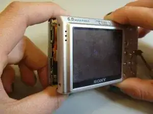
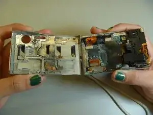
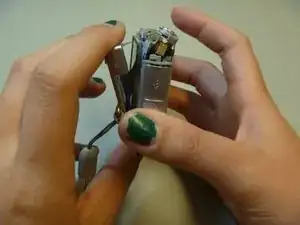
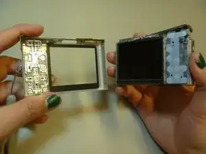
    • Gently pull the front cover off of the main camera.

    • All of the inner parts of the camera are attached to the back screen.

  6. tKTQKXoFTQaCbrrZ
    • The front cover is now removed from the camera and the internal hardware is now exposed.

  7. 6hl3hRyF4wgqFqRJ
    • This is the camera without the front cover.

  8. UPG4tHMDKuvwEj4Z
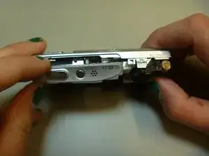
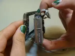
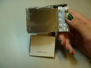
    • Remove tripod piece located at the bottom of the camera. This piece should slide out with ease.

  9. fqwfgEUfrxHJCP4a
    fqwfgEUfrxHJCP4a
    SeSUnuqnBoyHbs2K
    B6lrsB6aeABTDPBb
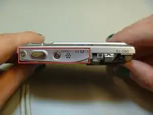
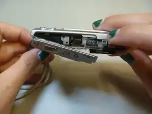
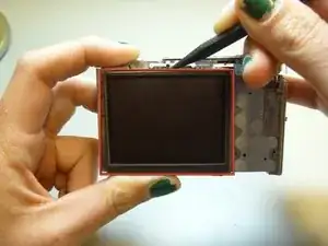
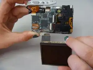
    • Slide open the top panel. This is located on the top of the camera, where the power button and shutter button are.

  10. EUTHwc4nAHRBLNJC
    EUTHwc4nAHRBLNJC
    ejwUERBfkspyeaMq
    AGSuPPgm5eXbIxrg
    • Pull apart the inner hardware from the back case by prying on the left side.

  11. fNupZxiLBxOWnjDh
    • Remove the back cover.

  12. vxICX46BG1xSFrWT
    • The back cover is now removed from the internal hardware.

  13. iyPdMXkg11XWB6Hi
    • Use the spudger to pry the LCD from the camera.

  14. QUr2hi6JgThn5QGQ
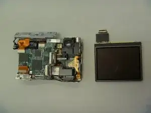
    • The LCD is now removed from the camera, although attached by a ribbon at the bottom of the camera.

  15. UXcfJw5IMgEKcIBB
    UXcfJw5IMgEKcIBB
    UHcyDpEHVG2lMFMg
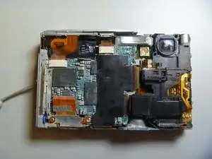
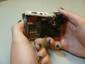
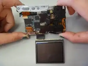
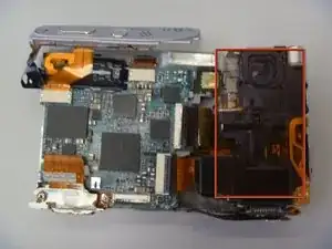
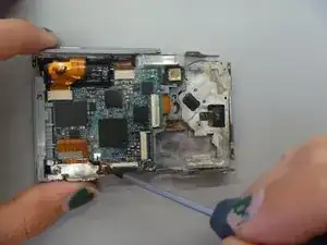
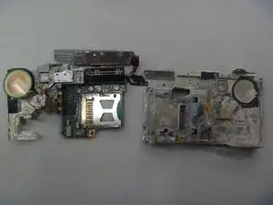
    • Flip camera to other side.

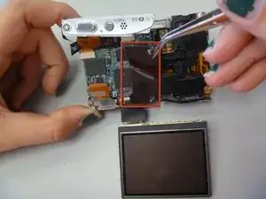
    • Use tweezers to peel off black sticker, located in middle of the motherboard.

  16. AROQUKmlDKJOKXIt
    AROQUKmlDKJOKXIt
    EEFs6hmtJhuADRtw
    • Use pry stick to pop out LCD connector ribbon, also called the ZIF connector.

  17. 3bq3Zrn4kJwUNfxN
    • The LCD is now removed from the camera.

  18. MxxaYSaP6pgR6sJH
    • This is the CCD module.

  19. CLimOvFmExu4vSFu
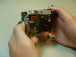
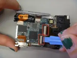
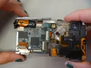
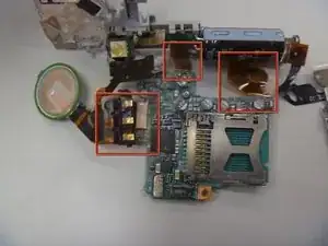
    • Use plastic opening tool pop open the two ribbons attaching to the CCD module.

    • These are the two ribbons.

  20. jmphpQuRBH2WFtYv
    • Remove CCD module.

    • You may have to tug on the ribbons to remove the CCD module.

  21. KLZICEjRVXCFjXeb
    • The CCD module is now removed from the camera.

  22. TjqiBk1D3JCsLnNY
    TjqiBk1D3JCsLnNY
    i6SpfJVqSWgKKIEX
    • These two screws hold in the AV port.

    • Use Phillips screwdriver to remove screws.

  23. YcARYEYvjQ4aAYYc
    • Remove metal screw plate.

  24. M1ZnNLntKBvZqg41
    • Use pry stick to pop off ribbon.

  25. nlKqqtFGVX1FhE4G
    • Remove AV port from camera.

  26. 5fvrYnmGRoLn3JnO
    5fvrYnmGRoLn3JnO
    6EASSlr5t1fMXXaW
    • The battery cover is located here.

    • Pull away from camera to remove.

  27. Fgy3RZQakWNNcpHv
    Fgy3RZQakWNNcpHv
    RtuurKDNO4HLwWuh
    • Grip on the top and bottom.

    • Pull up and out to remove motherboard and attached parts.

  28. fJDiNnhnpWOBUmdm
    fJDiNnhnpWOBUmdm
    JUWrgS2kPRF4AOWP
    rUmGpc6UidTaVmUY
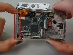
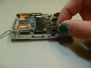
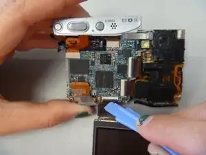
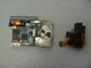
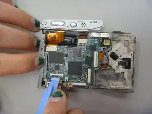
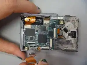
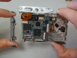
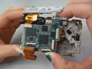
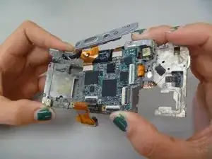
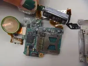
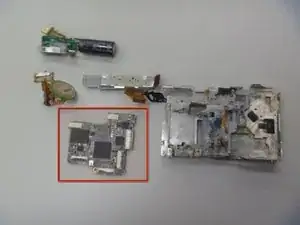
    • Flip motherboard parts to position shown.

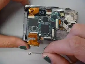
    • There are three ribbons still attached to the motherboard.

    • Pull these three ribbons to remove remaining parts from motherboard.

  29. HAX1vCMtKXLw1GSV
    • The motherboard is now removed from the camera.

Conclusion

To reassemble your device, follow these instructions in reverse order.

Stephannie Allen

Member since: 11/03/13

255 Reputation

One comment

Superb,thank you very much !!!

Vedrasco Victor Vasili -