Introduction
This guide gives step-by-step instructions on getting to the main internal component of the Cyber-shot DSC-T1 and then specifies how to detach them from the camera.
-
-
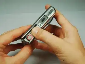
Locate the battery door at the bottom of the camera.
-
Press down on the door and slide it back. The door will pop open.
-
-
-
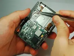
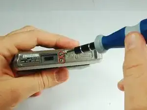
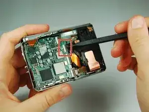
Use the tip of a spudger to flip up the tab on the ZIF connector securing the motherboard ribbon cable.
-
The second picture shows what these tabs look like in their open positions.
-
-
-
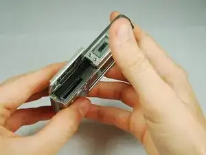
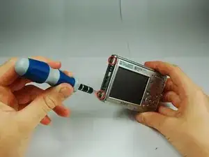
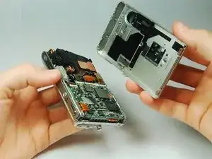
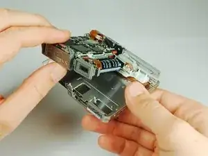
Carefully disengage the internal components from the casing by lifting at the bottom end and giving a gentle tug.
-
The components are still connected to the casing via cables, but they are much more maneuverable.
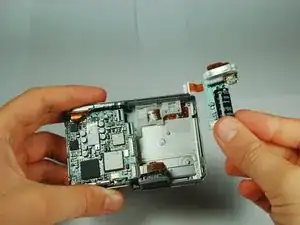
-
The flash module is shown on the right hand side.
-
-
-
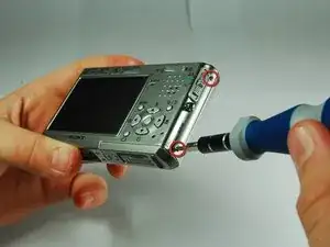
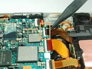
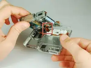
Use the tip of a spudger to flip up the tab on the ZIF connecter securing the motherboard ribbon cable.
-
Grasp the flash module by the bottom and remove it.
-
-
-
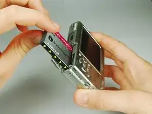
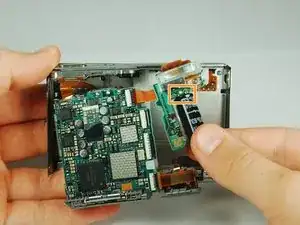
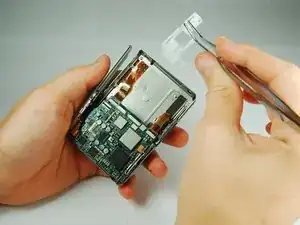
Use tweezers to slide the white piece on the back of the back cover to the right.
-
This will dislodge the white piece, allowing you to remove it from the back cover.
-
-
-
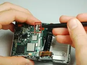
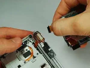
Use the tip of a spudger to flip up the tab on the ZIF connector securing the motherboard ribbon cable.
-
Remove the ribbon cables from these two ZIF connectors.
-
-
-
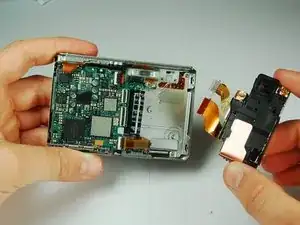
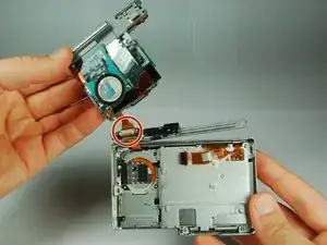
Lift the motherboard assembly up and rotate it so you can easily see where the internals connect to the back cover.
-
Remove the ZIF connectors from the clamp on the left end of the top piece.
-
The motherboard assembly is now separated from the back cover.
-

To reassemble your device, follow these instructions in reverse order.