Introduction
Use this guide to replace your camera lens. If you have determined that your lens is stuck or not working, it may be time to replace it.
No special tools are required for this procedure, and no soldering is involved.
Parts
-
-
This is a camera that will not turn on. It has a partially stuck lens. (The stuck lens prevents the camera from turning on.)
-
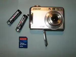
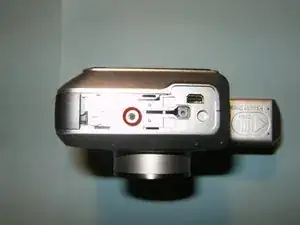
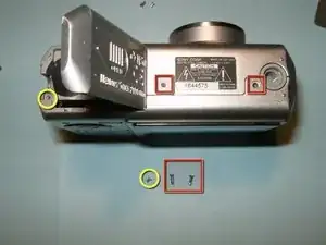
Open the compartment on the bottom of the camera. Remove the batteries and memory card.
-
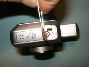
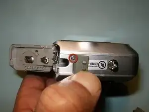
Turn the camera on its side, and remove the screw found under the USB-port cover.
-
-
-
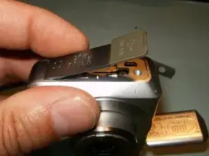
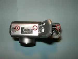
Remove the right middle cover.
-
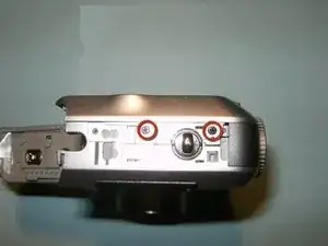
Remove the screw from the left middle cover.
-
Remove the screw from the right side.
-
-
-
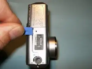
Split the case from the battery compartment side. Use a plastic tool to get it started.
-
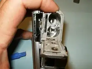
Once it is partially open, use your fingers to gently pull the case apart.
-
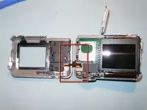
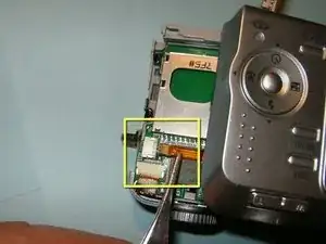
Do not try to totally separate the back case. It is still connected by a ribbon cable. Set the connected cases side by side.
-
-
-
The cable is just pushed into the connector. Use a pair of hemostats or tweezers to pull it straight out. Grab it close to the connector so that the cable wont tear.
-
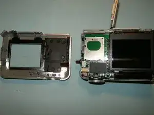
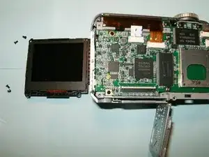
With the cable disconnected, separate the back-case from the camera.
-
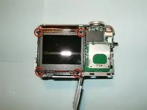
Remove the four screws from the LCD (Liquid-crystal display).
-
-
-
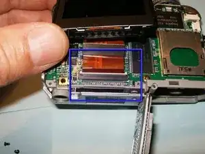
With the four screws removed, the connector for the LCD is easily accessed. Move the white clip in the opposite direction of the cable to open the connector.
-
Separate the LCD from the camera
-
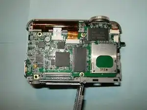
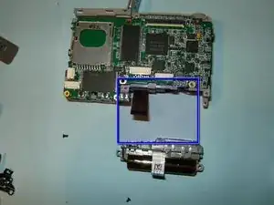
All the cable connectors and screws for the logic board are now fully visible. The cables are all a press fit.
-
-
-
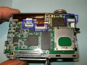
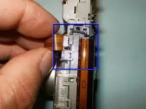
Remove the three ribbon cables. From left to right, the cables are for the flash capacitor, the lens, and the top control buttons.
-
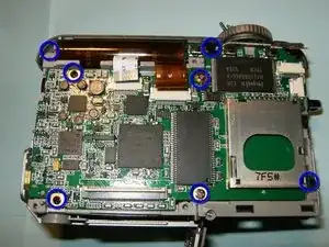
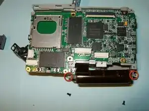
Remove the screws that hold the logic board, as well as the two long ones that attached the front case.
-
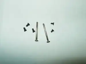
The screws are different sizes. Keep them separate. The two long ones will hold the front case to the camera, and they only fit in the middle of the logic board.
-
-
-
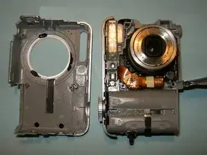
With the screws removed, the front case can now be separated.
-
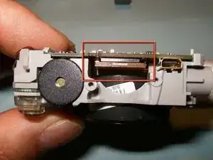
The upper block control button bar can now be removed. It is clipped on.
-
The lens ribbon cable is routed underneath the flash capacitor. It can be pulled, but gently.
-
-
-
To make assembly easier, remove the two screws that hold the flash assembly to the midframe.
-
This will give plenty of room to route the lens cable the proper way without risking ripping the cable.
-
-
-
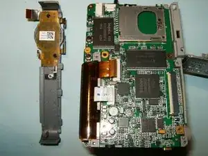
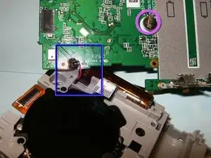
With all the screws removed from the logic board, there is now still the connector from the lens. Simply separate it by bending the cable in a downward direction
-
The logic board is still connected to the camera via the power cables. Do not try to remove the board. Fold it over instead. If the board needs to be replaced, the two wires would have to be desoldered.
-
View of the RTC battery
-
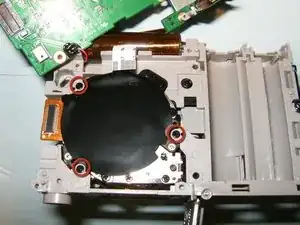
Remove the three screws that hold the lens to the camera.
-
-
-
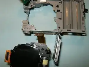
Remove the lens from the camera.
-
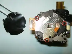
Remove the Kapton tape from the CCD sensor and remove the three screws.
-
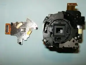
Separate the CCD sensor from the lens. The lens for this camera did not have the CCD sensor, so the old one was being reused.
-
To reassemble your device, follow these instructions in reverse order.

One comment
Wow- I JUST Wanted 2·Say Thank You So So Very Much 4·Taking The Time 2·Post All Of These ("D·I·Y·S·")Photo's & Instructions! I Used To Think, -Oh My Gosh- I Wish I Could Just Do This Myself Instead Of Having To Pay A Repair Shop Dang Near 1/2 My PayCheck 2·Do It-)) You've Saved Me A Lot Of Time &