Introduction
The Button Board is a pivotal and integral part of the device. Any improper handling can cause issues in other parts of the camera.Be sure to keep track of all pieces that are taken apart.
-
-
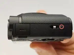
Remove the marked screw with a Phillips #000 screwdriver.
-
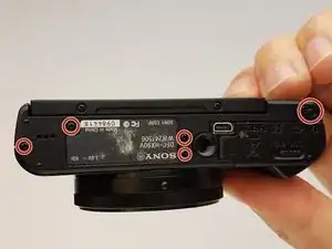
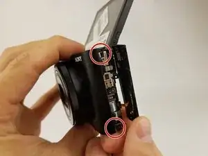
Remove the marked black M1.4 X 3.5 Phillips head screws
-
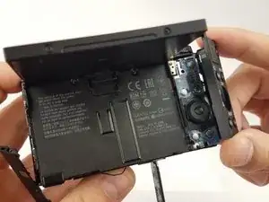
Use the spudger to gently remove the lower panel.
-
-
-
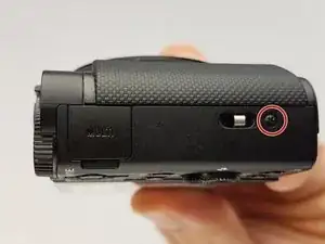
After removing the marked black M1.4 X 3.5 Phillips head screws with the Phillips #000 screwdriver on the side panel, using the spudger where the red arrow marks, insert and gently remove the side panel from the device.
-
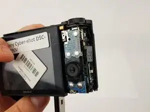
From either corner of the button board gently use hands to remove the button board.
-
-
-
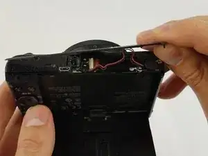
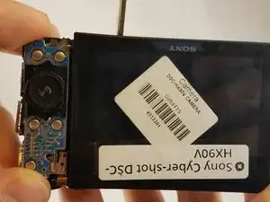
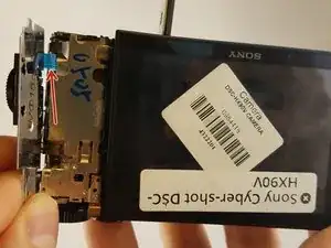
After the outer black panel case of button is removed, gently disconnect the control board data cable to the motherboard utilizing the tweezers gently where the red arrow marks.
-
To reassemble your device, follow these instructions in reverse order.