
Introduction
If viewfinder is broken or is not working properly you can follow these steps to replace it for a new one. These steps can also help in replacing shutter button and flash. For this guide you will need a PH000 screwdriver, a plastic tool opener, metal spudgers and a magnetic mat or plastic bag.
-
-
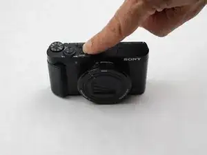
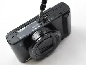
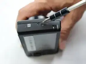
Before disassembling any part of the camera, turn off power by pressing down on the ON/OFF button. The ON/OFF button is located on top of the camera.
-
-
-
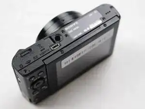
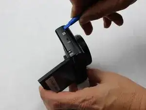
Open the compartment located at the bottom of the camera. Slide the LOCK/OPEN switch to the OPEN side. Locate the small blue tab on the side. Pull it in direction away from the battery. Remove the battery and set it aside.
-
-
-
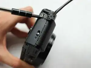
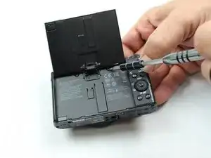
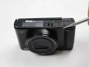
Use the PH000 Phillips head screwdriver (from iFixit tool kit) to take the screws out. Begin unscrewing from the bottom of camera. At the end of this step there will be a total of five black 0.4 mm Phillips screws. Place them on a magnetic mat or a plastic bag.
-
-
-
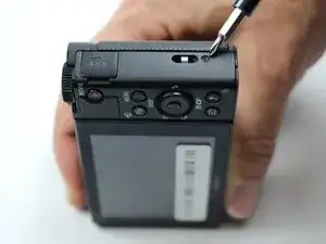
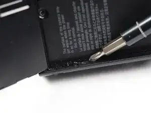
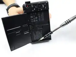
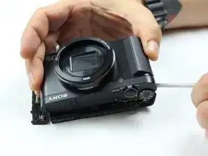
Keep working alongside the edge of camera until no screws are left in place. In addition to the five screws from the bottom, there will be a total of three more 0.4 mm black Phillips screws. Place them on the magnetic mat or plastic bag.
-
-
-
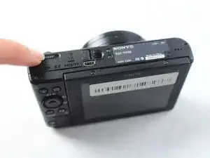
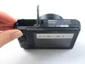
Flip LCD screen upwards.
-
Use the PH000 Phillips head screwdriver to remove screws located under the LDC screen. For this step there will be an additional three 0.3 mm black Phillips screws. Place them on magnetic mat or plastic bag.
-
-
-
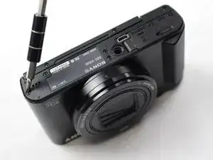
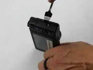
Use the plastic opening tools included in the iFixit tool kit first. If the shell/parts do not detach from each other, use metal spudger (from iFixit tool kit) to loosen/separate the plastic shell of the camera. Keep in mind there may be more screws holding parts together. Work delicately and separate sides evenly.
-
-
-
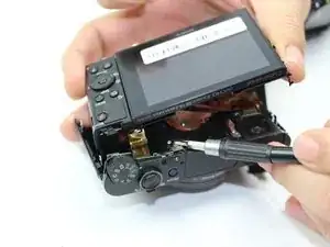
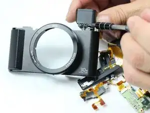
Locate the two silver screws that hold the top piece in place.
-
Use the PH000 Phillips head screwdriver to remove screws. Place the two 0.3 mm silver Phillips screws on magnetic mat or plastic bag.
-
-
-
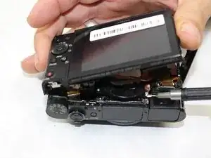
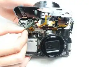
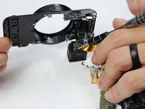
Use metal spudger to detach top part off the rest of the camera. Be extremely careful as there is a thin golden film/plastic ribbon holding the top piece to the rest of the camera.
-
-
-
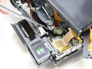
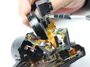
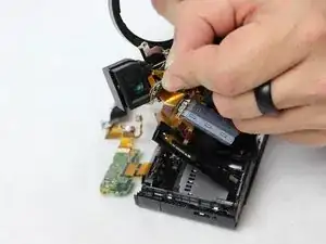
Look for the screws located on the circuit board. These screws are what allow the thin golden film/plastic ribbon to connect the top piece to the rest of the camera.
-
Remove circuit board screws by using the PH000 Phillips head screwdriver. Place the two 0.4 mm silver Phillips screws on magnetic mat or plastic bag.
-
-
-
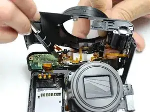
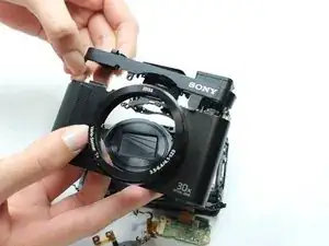
Gently pull the circuit board off the top piece of the camera. The top piece will be detached from the rest of the camera. Removing the top of the camera will make it easier to access the viewfinder.
-
-
-
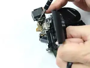
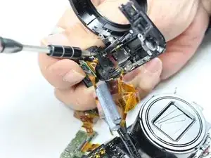
Locate the three 0.3 mm black Phillips screws around the viewfinder.
-
Remove screws by using the PH000 Phillips head screwdriver. Place the screws on magnetic mat or plastic bag.
-
-
-
Find one additional 0.3 mm black Phillips screw located at the bottom of the viewfinder. This screw attaches the circuit board to the viewfinder.
-
Remove the screw with a PH000 Phillips head screwdriver. Place the screw on magnetic mat or plastic bag.
-
-
-
After removing circuit board, find two 0.3 mm black Phillips screws located at the bottom of viewfinder. Remove the screws with PH000 Phillips head screwdriver. Place the screws on magnetic mat or plastic bag.
-
-
-
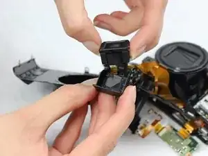
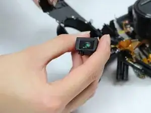
Gently remove the viewfinder from the plastic shell.
-
Replace the viewfinder with new viewfinder piece.
-
To reassemble your device, follow these instructions in reverse order.
2 comments
Hi, what is the part number(viewfinder)?
I would love it if someone could add a little piece here to show how to replace the flash unit as well.