Introduction
Though a malfunctioning shutter button is not common, it is believed that this guide would provide a means of extending the useful life of some Sony DSC-HX80 cameras, by providing a guide to allow for a replacement of the part rather than the entire camera.
Tools
-
-
Before disassembling any part of the camera, turn off the power by pressing down on the ON/OFF button. The ON/OFF button is located on top of the camera.
-
-
-
Open the compartment located at the bottom of the camera. Slide the LOCK/OPEN switch to the OPEN side. Locate the small blue tab on the side. Pull it in the direction away from battery. Remove the battery and set it aside.
-
-
-
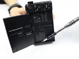
Use the PH000 head screwdriver to take screws out. Begin unscrewing from the bottom of camera.
-
At the end of this step there will be a total of five black 0.4 mm Phillips screws. Place them on a magnetic mat or a plastic bag.
-
-
-
Keep working alongside each side of the camera until all screws are addressed.
-
In addition to the five screws from the bottom, a total of three more 0.4 mm black Phillips screws are located as indicated in the photo. Place them on the magnetic mat or plastic bag.
-
-
-
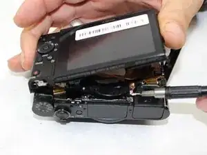
Flip the LCD screen upwards. Use the PH000 Phillips head screwdriver to remove screws located under the LCD screen.
-
For this step there will be an additional three 0.3 mm black Phillips screws. Place them on magnetic mat or plastic bag.
-
-
-
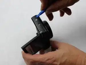
Use the plastic opening tools included in the iFixit tool kit first. If the shell/parts do not detach from each other, use metal spudgers as a last resort to loosen/separate the plastic shell of the camera. Keep in mind that there may be more screws holding parts together. Work delicately and separate sides evenly.
-
-
-
Locate the two 0.3 mm silver screws that hold the face of the screen in place. Use the PH000 Phillips head screwdriver to remove screws.
-
Place the two 0.3 mm screws on magnetic mat or plastic bag.
-
-
-
Use metal spudger to detach the face of the screen off the rest of the camera. Be extremely careful as there is a thin golden film/plastic ribbon holding the face of the screen to the rest of the camera.
-
-
-
After separating the face of the screen, look for the screws located on the circuit board. These screws are what allow the thin golden film/plastic ribbon to connect the top part to the rest of the camera. Remove the 0.4 mm circuit board screws by using the PH000 Phillips head screwdriver.
-
Place the two screws on magnetic mat or plastic bag.
-
-
-
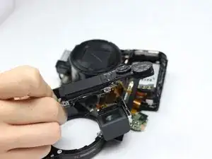
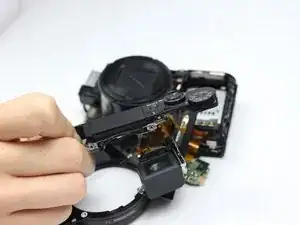
Gently pull the circuit board off the top piece. The top piece, which has the shutter button attached, will then be detached from the rest of the camera.
-
To reassemble your device, follow these instructions in reverse order.
