Introduction
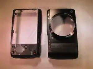
Complete replacement of the outer case requires complete dissassembly of the camera. This is a good time to replace other components if needed.
-
-
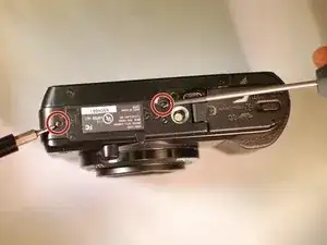
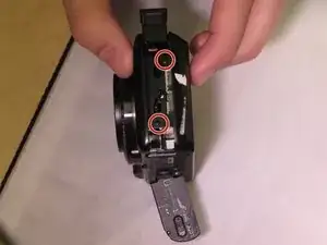
Remove these two black M1.4 X 3.5 Phillips head screws.
-
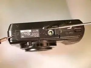
The third, unmarked screw does not need to be removed at this time.
-
-
-
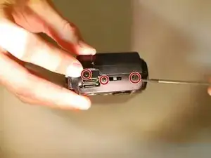
Orient the device so the LCD is facing you, and the hdmi cover is facing up ("left view).
-
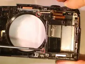
Remove these three black M1.4 X 3.5 Phillips head screws.
-
-
-
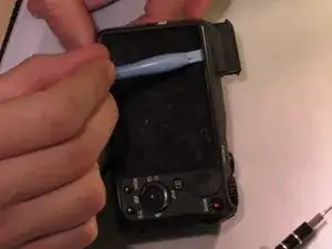
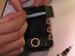
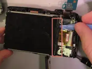
Use the plastic opening tool with a prying motion, going between the case and the LCD, from the middle of the LCD to the right of the device, undoing the claws retaining the back.
-
-
-
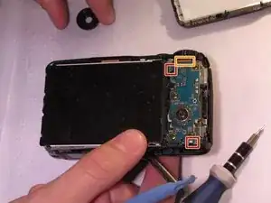
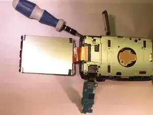
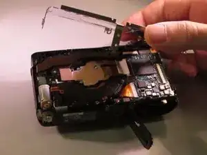
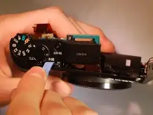
Unhook the small printed circuit board by gently pressing the board towards the top of the device and lifting up.
-
-
-
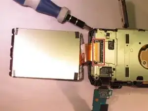
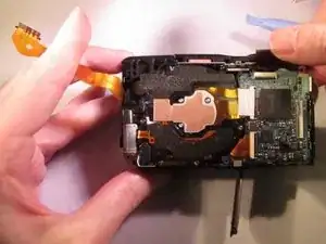
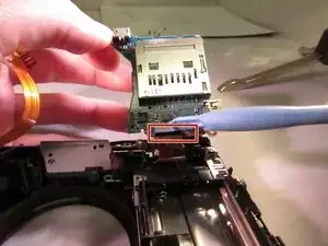
Using the plastic opening tool to lift the black retaining clip up to disengage the ribbon cable. Then gently pull the ribbon cable to remove.
-
-
-
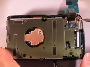
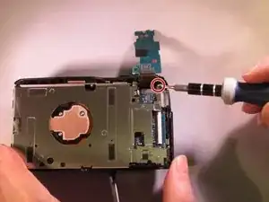
Remove the black M1.4 X 3.5 Phillips head screw in upper right corner of the device.
-
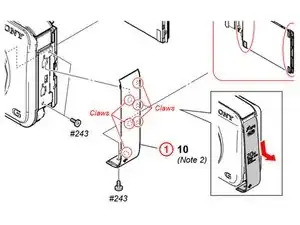
Service manual for reference: Click to go to the service manual.
-
-
-
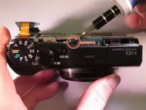
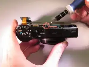
Reorient the camera so you are looking at the "top view".
-
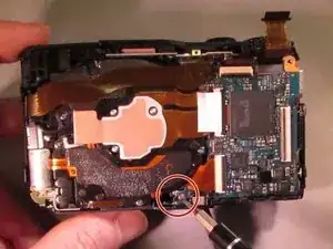
Remove the black M1.4 X 3.5 Phillips head screw next to the ON/OFF button circled in red.
-
-
-
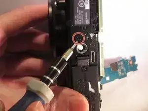
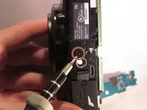
Orient the device so you are looking at the "bottom view".
-
Remove the black M1.4 X 3.5 Phillps head screw located next to the tripod attachment.
-
-
-
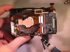
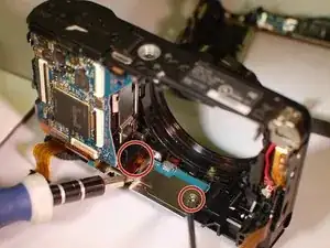
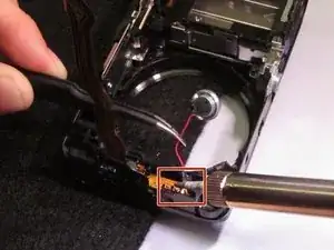
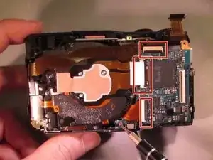
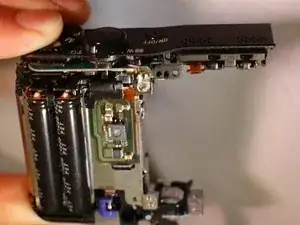
The connections (red squares) have small black retaining clips. Using a plastic opening tool, lift upward towards the cable to unlock.
-
The upper ribbon cable simply pulls loose.
-
-
-
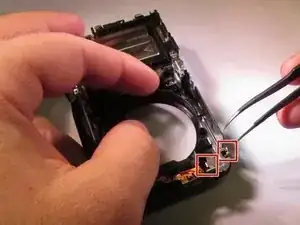
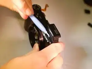
Use tweezers to remove the speaker retaining clip. The retaining hooks locations are indicated, but not exact.
-
-
-
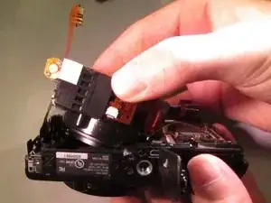
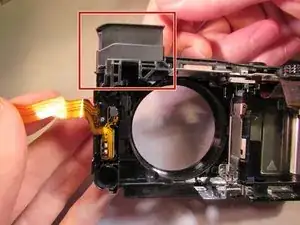
From the top of the camera, Use a plastic opening tool between the flash and the case to remove the flash.
-
-
-
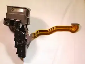
And here is the how the flash module should look after being removed.
-
This is a reference image: it is possible to further disassemble this module, and is not necessary.
-
-
-
Reorient the camera so you are looking at the "top view".
-
Remove the black M1.4 X 3.5 Phillips head screw just below the ON/OFF button circled in red.
-
-
-
Orient the device so you are looking at the "bottom view".
-
Remove the black M1.4 X 3.5 Phillips head screw located next to the tripod attachment.
-
-
-
The connections (red squares) have small black retaining clips. Using a plastic opening tool, lift upward towards the cable to unlock.
-
After detaching retaining clips, gently lift to disconnect the ribbon cables.
-
-
-
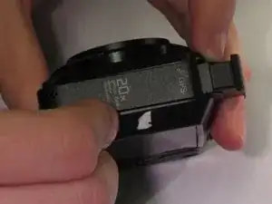
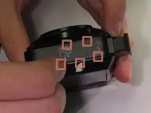
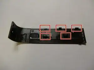
Using the plastic opening tool between the front edge of the camera and the top "control assembly", pry and unhook the claws roughly located in the red square.
-
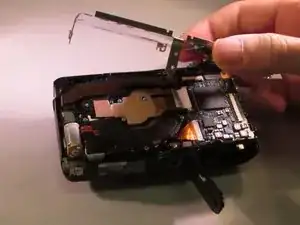

To reassemble your device, follow these instructions in reverse order.
2 comments
can i follow the same instruction for SONY DSC HX 10V .as both looks identical . when i shake my camera sound comes as if some parts are loosen but when i switched on my camera and the lens comes out that sound goes off . should i care for it or not ?
Thank you! Useful instructions.
Step 5 - perhaps a little more accurate step would be to lift up the bottom of the panel and then slide the panel downward. (reinstall in reverse direction).
I am having trouble orienting the control wheel - I tried to seat the middle button so it clicks and then set down the wheel on top but that does not seem to work after putting the back cover on. I’ve reopened and tried many times. Any suggestions on how to orient or reinstall the control wheel.
Gabe Zee -