Introduction
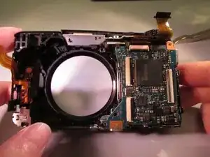
Replacing the motherboard may seem like a daunting task but can be done using prying tools.
Tools
-
-
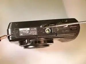
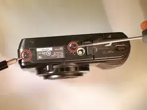
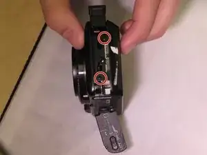
Remove these two black M1.4 X 3.5 Phillips head screws.
-
The third, unmarked screw does not need to be removed at this time.
-
-
-
Orient the device so the LCD is facing you, and the hdmi cover is facing up ("left view).
-
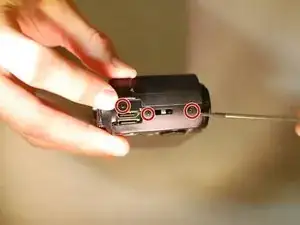
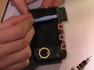
Remove these three black M1.4 X 3.5 Phillips head screws.
-
-
-
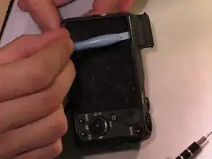
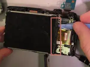
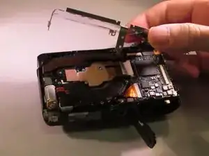
Use the plastic opening tool with a prying motion, going between the case and the LCD, from the middle of the LCD to the right of the device, undoing the claws retaining the back.
-
-
-
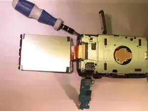
Unhook the small printed circuit board by gently pressing the board towards the top of the device and lifting up.
-
-
-
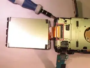
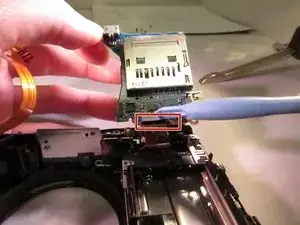
Using the plastic opening tool to lift the black retaining clip up to disengage the ribbon cable. Then gently pull the ribbon cable to remove.
-
-
-
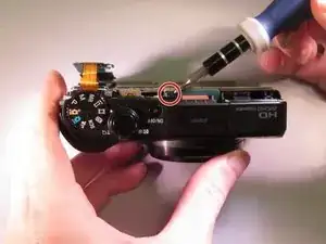
Reorient the camera so you are looking at the "top view".
-
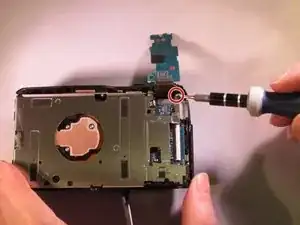
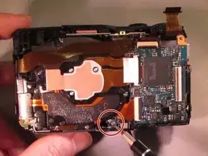
Remove the black M1.4 X 3.5 Phillips head screw just below the ON/OFF button circled in red.
-
-
-
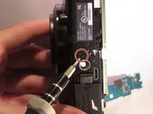
Orient the device so you are looking at the "bottom view".
-
Remove the black M1.4 X 3.5 Phillips head screw located next to the tripod attachment.
-
-
-
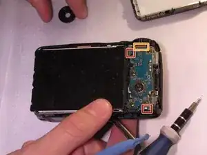
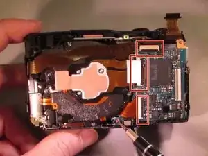
The connections (red squares) have small black retaining clips. Using a plastic opening tool, lift upward towards the cable to unlock.
-
After detaching retaining clips, gently lift to disconnect the ribbon cables.
-
To reassemble your device, follow these instructions in reverse order.
