Introduction

This guide will help you to replace the top panel on the Sony Cyber Shot DSC-W170.

If the shutter button or the power button are not working properly, the solution is to replace the top panel unit. Be sure to remove power/disconnect batteries before performing this task!

Take a look at our troubleshooting page if you need help to remove the battery.

On the Sony website you can find replacement parts for the camera.

  1. PJEam5hJkMDu2fie
    PJEam5hJkMDu2fie
    glKXQFNLwMBovXkh
    mWIhjtmKNjQIrOjw
    • Be sure to remove the battery before performing this task.

    • Remove the five 4 mm screws with a Phillips #000 screwdriver.

  2. fMiJ2IlulDWXv6JG
    • Use an opening pick to pry the LCD panel open.

  3. tImvaenn6lDlOxfe
    • Gently remove the LCD panel from the rest of the camera.

  4. ZYkL5mOLJEROdnLW
    ZYkL5mOLJEROdnLW
    InxoGGmNTkIXZOXU
    NdTOBWrijGgJ2eOY
    • Remove the three 4 mm screws with a Phillips #000 screwdriver.

  5. LbKbawWiNhCchEge
    • Gently open the front panel and remove it from the rest of the camera.

  6. XB5slA3DXDat2kTK
    XB5slA3DXDat2kTK
    DOkNp5gaWXVfRC6q
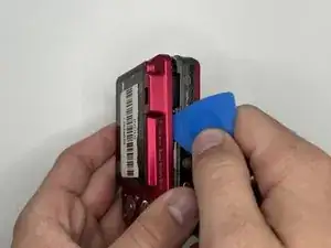
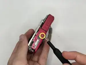
    • Remove the first side panel to the left of the LCD.

    • Remove the 4 mm screw from the other side panel to the right of the LCD with a Phillips #000 screwdriver.

  7. VPS2hZRpsL3cy3tr
    VPS2hZRpsL3cy3tr
    ldaA5cfAuh4aCW32
    WBC5Rl4o22DlBlxC
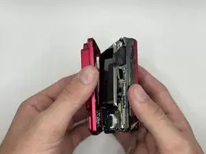
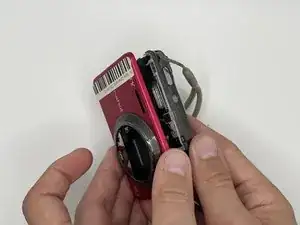
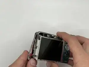
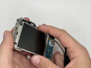
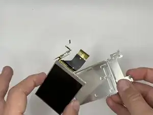
    • Gently, lift the LCD and carefully open the camera to disconnect the LCD ribbon cable from the motherboard.

  8. WcBRBkoUeFMeSRgi
    WcBRBkoUeFMeSRgi
    HJVXHxnAqUiiyLng
    • Gently push the connector through the hole to separate the LCD from the metal casing.

  9. mIsuREXg3ZFIHiTT
    mIsuREXg3ZFIHiTT
    QSwXkF5PPX4glMBw
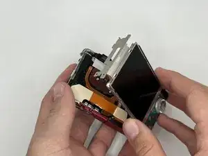
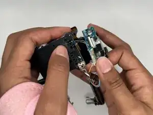
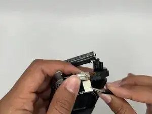
    • Lift up the black bar on the top flat ribbon cable with tweezers.

    • Gently pull the flat ribbon cable until it disconnects from the lens assembly.

    • Be gentle when dealing with the flat ribbon cable.

  10. jxmEfwSIvibGXWHL
    jxmEfwSIvibGXWHL
    yABMRaCoDlR5Ug1W
    ipGpJgovFefdp6qY
    • Remove the six 4 mm screws from the lens assembly with a Phillips #000 screwdriver.

  11. IdNxFOFQTnj6qIRa
    • Lift the two flat ribbon cables with tweezers.

  12. kVHr3twmWRcAGfWI
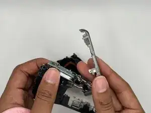
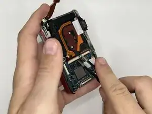
    • Peel back the flash assembly on the back of the lens.

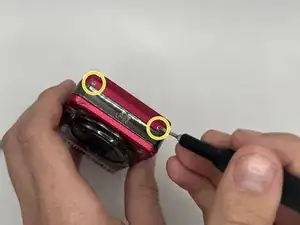
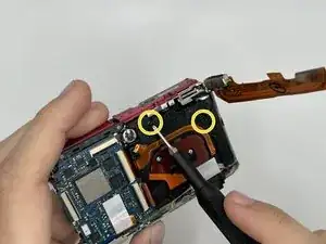
    • Remove the two 4 mm screws with a Phillips #000 screwdriver.

  13. wOSSUJGdRQbUIIvi
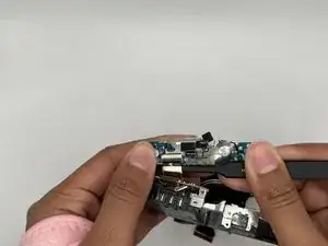
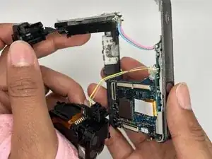
    • Pull out the battery from the side and remove the white tape from the battery assembly with tweezers.

  14. roOFKLdVObYLT1JX
    roOFKLdVObYLT1JX
    5VmpJnfI3AbcArvu
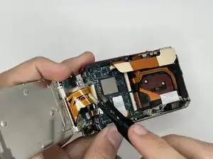
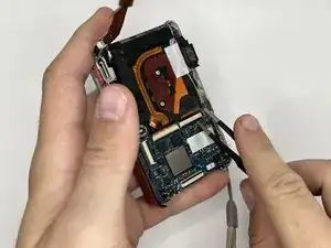
    • Disconnect the flat ribbon cable that connects the motherboard to the lens assembly with tweezers.

  15. xsD5FRALook4XmvL
    • Push out the lens assembly very gently.

  16. KOtHTbEGEsO4RGBQ
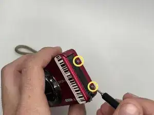
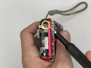
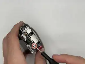
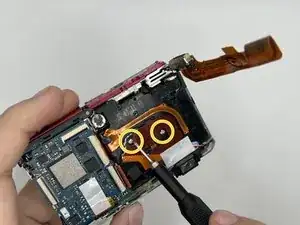
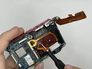
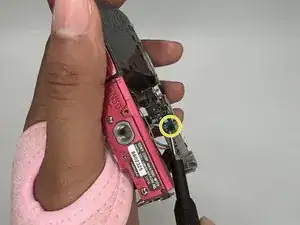
    • Remove the 4 mm screw from the bottom side of the top panel with a Phillips #000 screwdriver.

  17. axChMXNN3IslyZNS
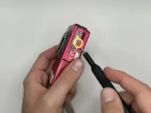
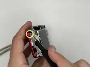
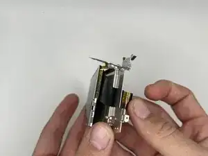
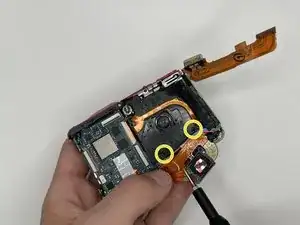
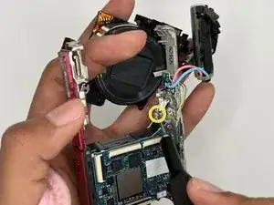
    • Remove the silver 4 mm screw with a Phillips #000 screwdriver from the silver bracket connected to the motherboard.

  18. LCJhSHNQtWNSA1Pm
    • Pull the top panel off gently.

Conclusion

To reassemble your device, follow these instructions in reverse order.

Katharina Anglett

Member since: 13/09/23

529 Reputation

0 comments