Introduction
For this guide you will be replacing the LCD screen as a unit. It is sold as an electronic assembly including an electronic board, connecting ribbon and the screen itself. To replace this part you will need precision set of screw drivers, and a set of plastic opening tools to "pop" open the clips.
We have not found an inexpensive supplier for this part. It may be cheaper to purchase a used or broken SLT-A55V for parts.
-
-
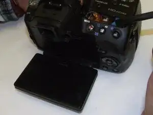
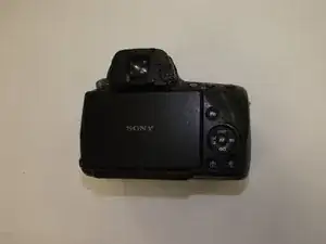
The LCD screen is located on the back of the SLT-A55V.
-
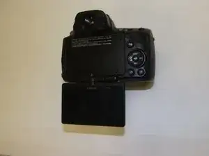
The screen folds out and can be rotated to view in several orientations.
-
-
-
Start the replacement by removing the rear cover of the camera.
-
The rear cover is attached with several screws on four sides of the camera. On the left side there are two screws near the clip for the wrist strap.
-
-
-
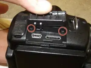
On the same side as the previous step lift the rubber flap that covers USB and the HDMI ports.
-
Remove two screws.
-
-
-
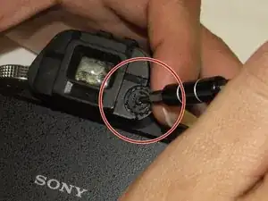
Remove the screw that attaches the focusing adjustment for the eyepiece. The focusing wheel will also be removed.
-
-
-
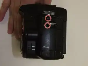
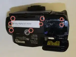
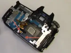
On the bottom of the camera remove seven screws indicated by the circles in the picture to the left.
-
-
-
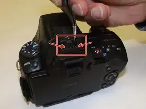
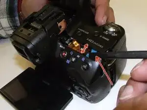
On the top of the camera there is a black plastic sticker that hides two screws which must be removed.
-
This sticker can be re-used. Peel the sticker off and place it on a clean piece of parchment paper or wax paper. This will prevent dirt and dust from getting on the adhesive.
-
Remove the two screws that lie beneath the sticker. The arrows indicate the location of these screws.
-
-
-
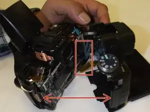
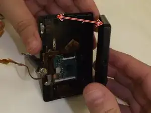
Using a nylon spudger, gently pry the cover open.
-
To do this step properly without damaging the back cover it is necessary to pry open the cover incrementally around the perimeter of the case.
-
-
-
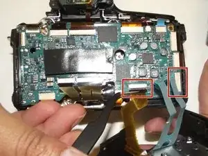
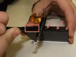
Unplug the ribbon cable indicated by the arrow on the left of the picture.
-
The arrow pointing to the black area indicates another sticker. This sticker will need to be removed in order to thread the ribbon cable through the back cover. This cable is attached to the LCD panel.
-
-
-
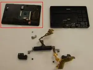
Unplug the ribbon cable from the LCD screen.
-
Replace the LCD screen and re-assemble in reverse order of these steps.
-

To reassemble your device, follow these instructions in reverse order.