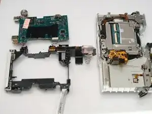
Introduction
-
-
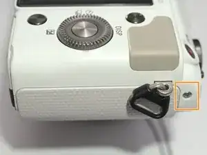
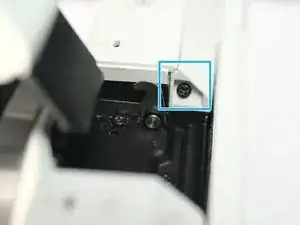
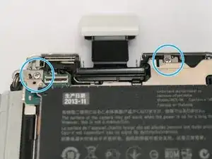
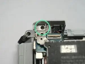
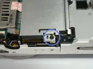
Right side, remove 1 M1.4x3.7 screw
-
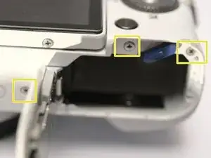
Left side, remove 3 M1.4x3.7 screws
-
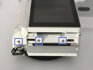
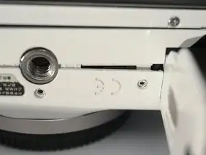
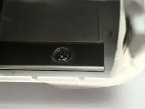
Bottom side, remove 5 M1.4x3.7 screws, including 2 in battery bay. 2 of them out of this photo, you can find them.
-
-
-
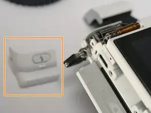
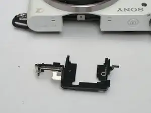
Remove LCD hinge cover, by sliding to the left.
-
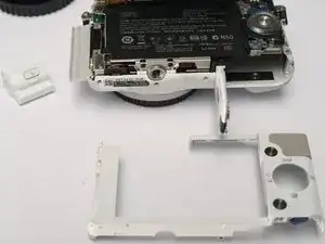
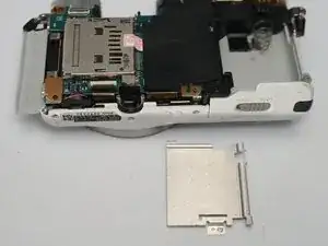
Remove back cover, actually just a plastic frame.
-
-
-
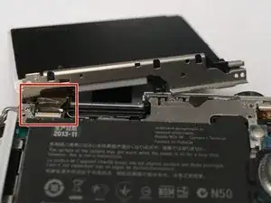
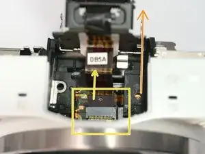
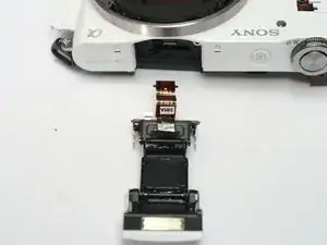
Slide the flash assembly backwards with caution.
-
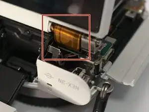
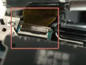
Detach flash FPC by pulling it out of the socket.
-
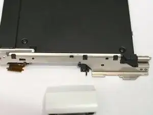
Then remove the flash assembly.
-
-
-
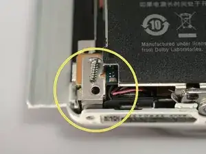
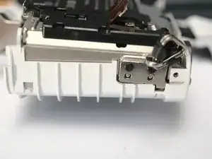
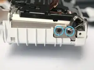
Remove 2 ST1.7x5 screws from inside the battery bay. (one of them not shown, deeper inside) insert screw driver through a hole in the shielding cover.
-
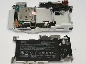
Pop the grip off. From back, push to the right, then it flies forward.
-
-
-
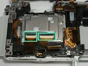
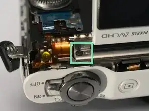
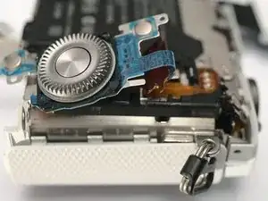
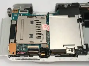
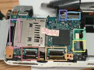
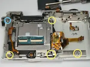
Sensor power, flip
-
Sensor signal, flip
-
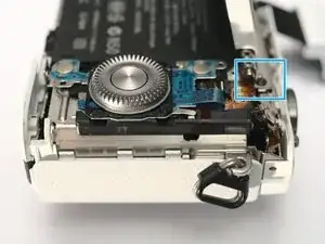
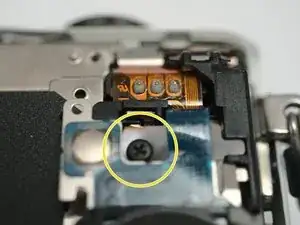
Shutter, pull
-
Lens contacts, pull. Did I mention that Sony makes world's most brittle FPC?
-
Whatever, pull
-
Whatever, pull
-
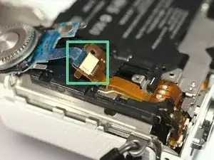
Shutter charger motor FPC, (backside, pull out)
-
-
-
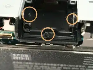
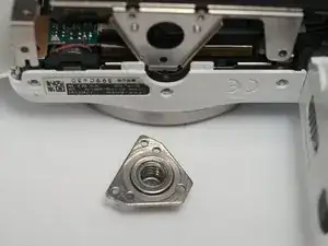
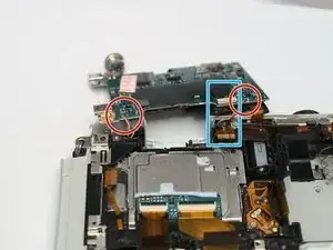
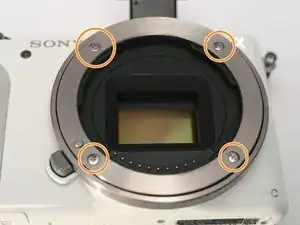
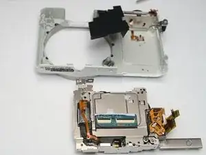
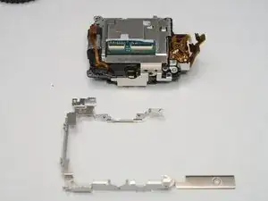
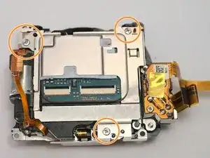
Remove 3 ST1.7x5 screws
-
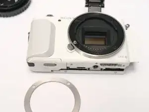
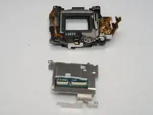
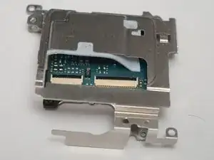
Remove sensor shield / heat sink. Sensor PCBA might sticks to the shield, just separate them.
-

To reassemble your device, follow these instructions in reverse order.