Introduction

The viewfinder glass helps you frame the scene before taking the photo. A broken viewfinder glass will affect your ability to compose good pictures. This guide will walk you through the replacement of a broken viewfinder glass. Ensure that the problem with your viewfinder is not software related, and verify that the focus feature is working properly before considering replacement. The tools required for this replacement are a JIS 0 screwdriver, JIS 00 screwdriver, JIS 000 screwdriver, opening tools, spudger, and tweezers.

  1. o4UEXCXeOUZjkviI
    • Verify the camera is powered off by setting the switch to OFF.

  2. dCHOBRPuMTTqHmIA
    dCHOBRPuMTTqHmIA
    dkJxRoZhPoghIxUK
    • Flip the camera upside down.

    • Slide the battery compartment lock to OPEN to unlock it.

  3. HqAeBfgUIE26Bh4E
    HqAeBfgUIE26Bh4E
    1GOlaeTsR1cCocn4
    • Push the blue lever aside to release the battery.

  4. XZKs2ArxSb1UNmEU
    • Remove the released battery from the compartment.

  5. SAfHCcobPiNMPoBQ
    SAfHCcobPiNMPoBQ
    6QQeQMXrVEEQBfqP
    • To access the back of the camera remove the screws attaching the LCD screen hinge to the camera body.

    • Remove four 3 mm JIS 000 screws.

    • Remove one 3 mm JIS 00 screw.

    • After dismounting the screen hinge be careful to avoid tearing the black wire ribbon connecting the screen to the camera body.

  6. ObokFwlOS6N6ac2C
    ObokFwlOS6N6ac2C
    iZxCFQqsKYv5sfoQ
    • Grasp the viewfinder eyecup; slide it up and off the viewfinder.

    Insert an arrow to show which way is up.

    Simon Lin -

  7. 2qdgMpNN4WgAWQTc
    2qdgMpNN4WgAWQTc
    1JUQNll2VYwCsChR
    pGfxCihfeVcViBIT
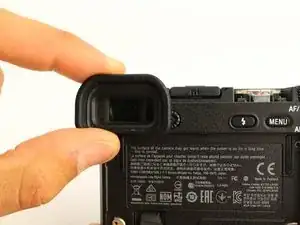
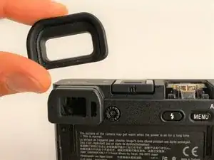
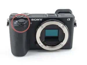
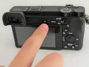
    • Press the flash popup button on the back of the camera.

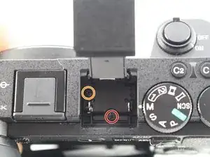
    • Remove one 5 mm JIS 00 screw from inside the flash compartment.

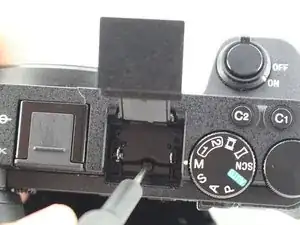
    • Remove one 4 mm JIS 00 screw.

  8. Eqvo31rxZirdqcPM
    Eqvo31rxZirdqcPM
    VQ2vJ2QPPH41bZCA
    TJVBAbO6R3JTXSKT
    • To remove the top of the camera you must remove the back first.

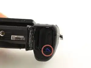
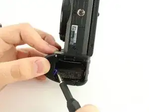
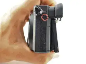
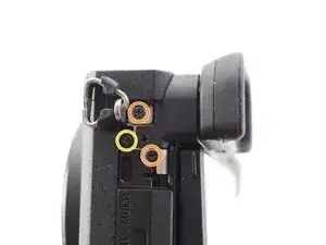
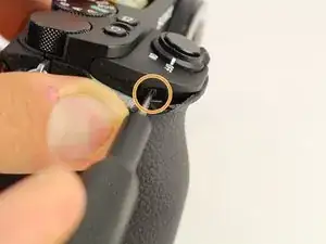
    • Remove the 2.5 mm JIS 00 screw from the side of the camera near the viewfinder.

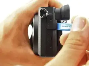
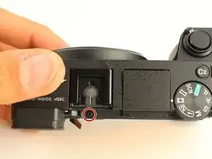
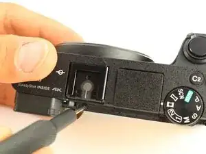
    • Use the opening tool to pry off the small cover.

    • Remove two 2.5 mm JIS 00 screws from underneath the cover.

    • Remove a 5 mm JIS 00 screw from underneath the cover.

    Should the first one (red) be 4mm?

    brendon.coetzer -

  9. AHCNHvB5oGvXU1km
    AHCNHvB5oGvXU1km
    IRKSsfLrUEPx5TFP
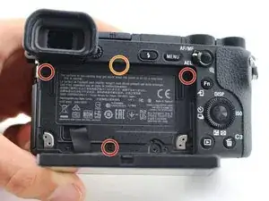
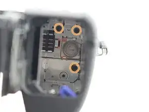
    • Remove three 2.5 mm JIS 0 screws from the back face of the camera.

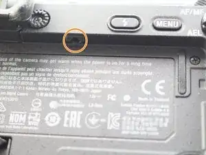
    • Remove one 4 mm JIS 00 screw from the underside of the lip that overhangs the back of the camera.

  10. UfHgPDhIYpoopaoK
    • Remove four 4 mm JIS 0 screws from the bottom of the camera.

  11. JGqmO1Ms6vLZfxEK
    JGqmO1Ms6vLZfxEK
    BFQkV4S4ZAV2wirr
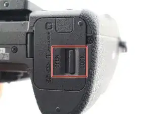
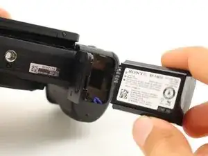
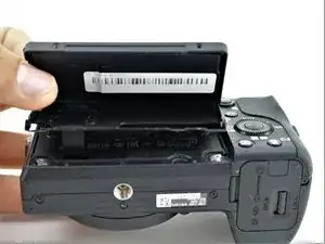
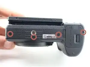
    • Flip the battery lock switch to open and open the battery compartment.

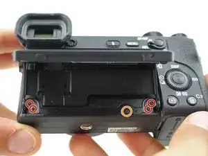
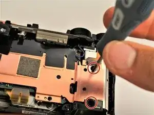
    • Remove three 2.5 mm JIS 00 screws from the top of the battery compartment.

    • You may need a longer or thinner screwdriver to reach the screws in the battery compartment.

    These 3 screws were 4mm on my camera. Mine may have been disassembled previously.

    jkenny23 -

  12. P4doNA3VjuqSkB3f
    P4doNA3VjuqSkB3f
    svLVyDTDSKUKXVpR
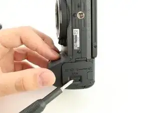
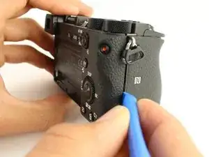
    • Use the plastic opening tool to begin prying off the back of the camera from the side.

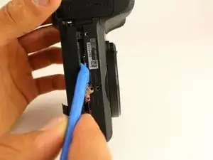
    • Continue to loosen the back until you can open it from the bottom.

  13. SGsNOuyUsNFqiYrh
    SGsNOuyUsNFqiYrh
    Kb5KjEI1UhBDPm1y
    iSGhiiNZ2jtnKqG4
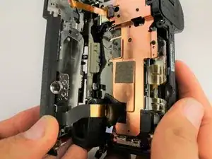
    • Open the back of the camera.

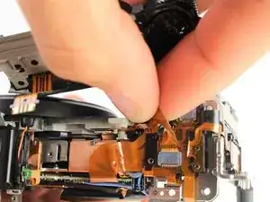
    • Use tweezers to remove two ribbon connectors from underneath the back. One connects to the LCD display and the other connects to the right side behind the battery compartment.

    • Ribbon connectors can tear easily. Grasp the plastic ends (not the ribbon) when removing.

  14. OehQTIbmqLQPQ1Hb
    OehQTIbmqLQPQ1Hb
    a6Ue1hXGdMGXC5Pm
    oG2WiY3bTSrLsqGI
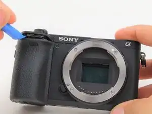
    • Use the plastic opening tool to peel down the rubber grip around the handle at least 1 cm.

    • The adhesive holding the rubber grip down should be strong enough to reattach when you are done. If not, you may need an adhesive to reglue it.

    • Remove one 3 mm JIS 000 screw from underneath the rubber grip on the right side.

    • Remove one 4 mm JIS 000 screw from the left side.

    Left side contained a 3mm screw as well on my camera. Mine may have been disassembled previously though.

    jkenny23 -

  15. UmQBvqPyDWkYeOft
    UmQBvqPyDWkYeOft
    XAy4E1gB4x4AnhIf
    • The last screws holding the top on can be accessed once the back of the camera is removed.

    • Remove one 2.5 mm JIS 00 screw from the top next to the flash mount.

  16. EOeYNMcMoOZxZkI1
    EOeYNMcMoOZxZkI1
    IXTKIrdQ1OTnlJLQ
    UaGqOjFBL5CLrNAa
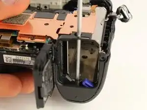
    • Insert a long, thin JIS 00 screwdriver through the two holes and into the battery compartment; remove the two 5mm JIS 00 screws inside it.

  17. PKN4cvbkZCEsOVZW
    PKN4cvbkZCEsOVZW
    STgpExpcS2L3DL6W
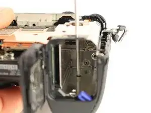
    • Use the long, thin, screwdriver to remove one 5 mm JIS 00 screw inside the camera accessible below the dials from the back.

    is there a simple way to remove that knob what is switching between programs (Manual, Shutter Priority, Aperture Priority)

    My camera, during video recording is swithing by herself between programs and at the same time stopping video recording, and I’m thinking that maybe it needs a bit of contact cleaning

    Daniel Croitoru -

  18. nIRJIoHOfIWw3WPL
    nIRJIoHOfIWw3WPL
    vgVVloeIywgYhnKp
    4xVdWYyDXHManvDK
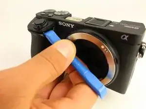
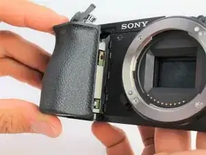
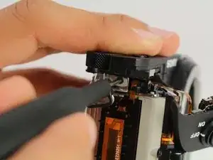
    • Use the plastic opening tool to gently lift up the shutter button assembly.

    • Grasp the front grip from the top and bottom and pull it off. It should come off easily with the shutter button out of the way.

    • The shutter button will still be attached by one ribbon cable once the front grip is removed.

    Can you do a teardown of the top from a sony a6400? Because this from part with the shutter button is not separate as in a6500, in the a6400 is part of the top as a one piece and I havent found any dissassembly process for the a6400.

    artur_jeronimo -

  19. SOcusitKcXLTllNF
    SOcusitKcXLTllNF
    BKbUHSCIhQwJGZVI
    PEoGJ222nPBPuryJ
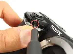
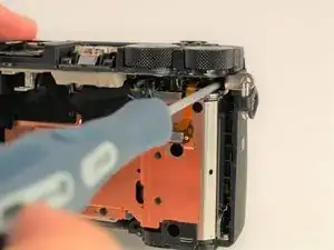
    • Remove one 2.5 mm JIS 00 screw from where the shutter button assembly used to be.

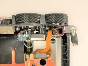
    • Remove one 3 mm JIS 00 screw from the side of the camera.

  20. AdEjWAlCSPrtJnVW
    AdEjWAlCSPrtJnVW
    biICwYRiuLxuvf4T
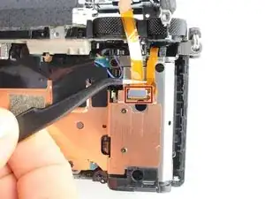
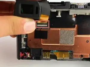
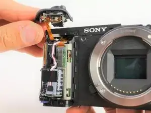
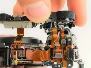
    • Carefully unplug the two ribbon connectors attaching the top assembly to the rest of the camera.

    How can I plug the flash ribbon connector back in when reassembling the camera? I successfully replaced the flash, following your guide, but now I am stuck as I can't figure out how to plug that connector in. The plug appears to be hidden.

    Christa Rohrbach -

  21. dUBV1odV1AcNJo3T
    dUBV1odV1AcNJo3T
    gVqjP3TdhwoVwjWn
    325AK1iW5iiiNmuF
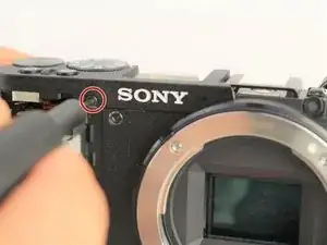
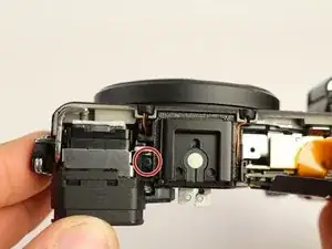
    • From the top of the camera remove one 4mm JIS 00 screw.

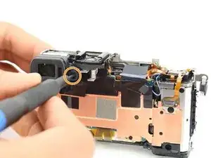
    • Remove one 5mm JIS 00 screw and the plastic bushing around it.

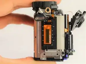
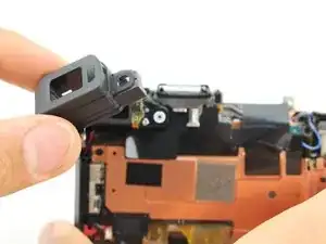
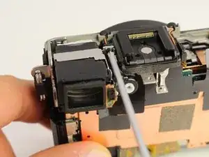
    • Remove the viewfinder's protective cover.

  22. AouAeegJEMbDtpXI
    AouAeegJEMbDtpXI
    D2BQ3iusqPsMp5lK
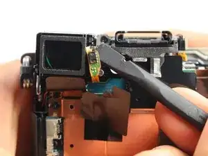
    • Use the spudger to pry the light sensor off the side of the viewfinder.

    • When prying off the sensor, bend it out from the bottom.

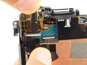
    • Remove one 2.5mm JIS 000 screw on the side of the viewfinder to release it.

  23. WQTmAZiPs5u4mgUI
    WQTmAZiPs5u4mgUI
    aHiu2XZBL6RqYjRC
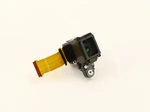
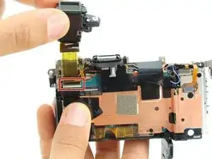
    • Lift the viewfinder out and flip up the tab to release the wire ribbon where it is connected to the motherboard.

Conclusion

To reassemble your device, follow these instructions in reverse order.

Jackson Furie

Member since: 10/10/19

801 Reputation

2 comments

This really helped me. I changed my VF unit with no problem. And btw, it is not necessary to unplug LCD cable. I havent done it, as i thought it would be really tricky to put it back in and it was just alright. Just tape the display to back panel while manipulating it so you dont twist the cables.

Adam Barus -

Thanks for this
Where can I get the viewfinder glass though

Kojo Erskine Coffie -