Introduction

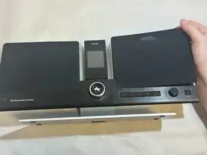
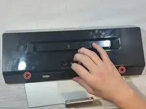
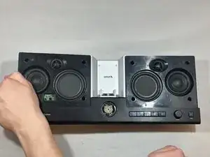
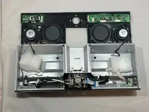
The bulk of the work for this guide is removing the front plate. Sirius put in some serious effort to keep it from ever coming off.

The Aux board may become damaged with frequent use as stresses are applied via the attached headphone jack port. It is relatively simple and fast to remove.

  1. BdpREpHWoBHnNMDh
    BdpREpHWoBHnNMDh
    hkyhSHr3MieCbNgb
    C2GU1kkDVnfr6MiM
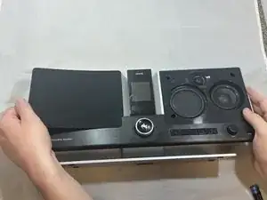
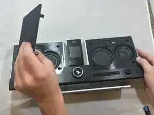
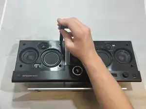
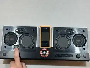
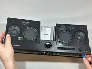
    • Pry the speaker covers up gently from their sides by pulling up on the four corner posts that hold the cover in place.

  2. JhQQovBUuQA3VDli
    JhQQovBUuQA3VDli
    glcSlT2BSHwKKEaF
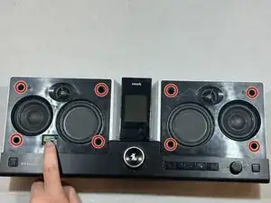
    • Remove the eight 11 mm screws from the front plate using a Phillips #1 screwdriver.

  3. SLHHjrf2FnpWp23l
    SLHHjrf2FnpWp23l
    Sot5pYL2oQLD1bZK
    5obCkfm2ACIlsFUy
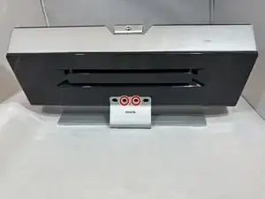
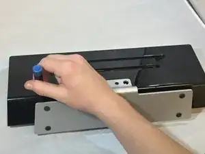
    • Turn the device so its back is facing you.

    • Remove the two 11 mm screws using a Phillips #1 screwdriver.

    • Separate the stand from the device.

  4. DFf2DwaQXuUWUiZ4
    DFf2DwaQXuUWUiZ4
    QDYiekhlLlGOfDOk
    iHA6i5R6LAyNAZIA
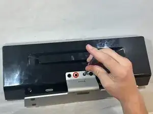
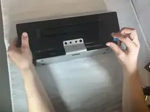
    • Remove the two 9 mm screws with a Phillips #1 screwdriver.

    • The screws will be buried slightly into the frame.

  5. CYwn6MLdWMYgePED
    CYwn6MLdWMYgePED
    6Sep4HK516miX2yC
    ZluQOqwX61kI1yEv
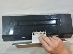
    • Turn the device so that its front is visible.

    • Remove the channel dial by pulling up on the dial firmly.

    • Remove the S50 by pulling it up and off of its connecting posts.

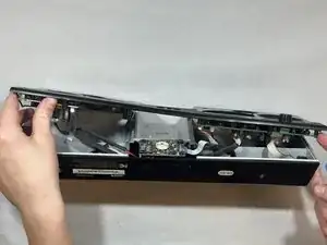
    • The front plate is now removable, but has a fairly strong adhesive so extra force will be required to pry it open.

    • Use an iFixit opening tool to pull up both sides of the speaker plate. They should come up easily. Pull firmly on the center to break the adhesive.

  6. AIfaxfYhFKqPAIkm
    AIfaxfYhFKqPAIkm
    agWLkQlEsXcdTR1N
    CCZ6esWrQ1vdeYEJ
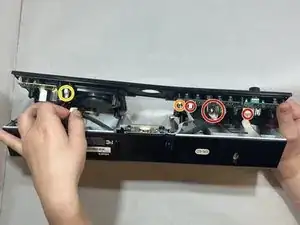
    • Once the face place comes free, it will still be held in place by five connecting pieces.

    • Remove the three bundled-cable wires.

    • Remove the ribbon cable connector.

    • Remove the power connector cable.

    • The connecting points are delicate. To ensure that no damage comes to the device please use both hands to firmly disconnect each without wobbling.

  7. UuqItOSeMXTAWHHu
    UuqItOSeMXTAWHHu
    CCa3dSvGvXJvTfXm
    B5PtHSSEFjv4jUX3
    • Remove the single 8 mm screw using a Phillips #00 screwdriver.

    • Disconnect the bundled cable connecter from the board.

Conclusion

To reassemble your device, follow these instructions in reverse order.
Harley Cejka

Member since: 02/10/23

533 Reputation

0 comments