Introduction

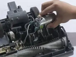
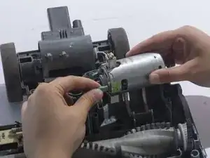
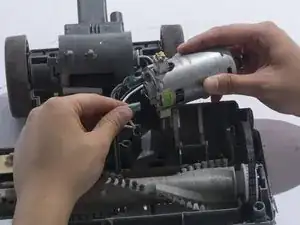
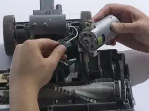
The motherboard is the command center for the vacuum's functions. Sometimes components on the board will come loose and require replacement. This guide will show you the steps necessary to replace the motherboard.

  1. nFIlnTIDJTnKmxfX
    nFIlnTIDJTnKmxfX
    tvXqJSpb4rTWFymC
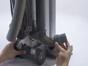
    • Detach the hose connected on the bottom of the vacuum by pulling it out of the casing.

  2. pMX2EBNdfeYXu3De
    pMX2EBNdfeYXu3De
    YNn5LAnCM4VOKsII
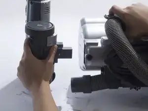
    • Lay the vacuum on its side.

    • Press in the black, rubberish button located on the back of the vacuum to detach the vacuum head from the body.

    wow, that black button stumped me. who would’ve thought the head would detach. the little hose is really stuck to the head. like it’s gonna break. wd-40?

    Rodney Kahn -

  3. EyncXJYlXAhoJoOW
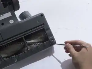
    • Flip over the vacuum head so the brush head is facing up.

  4. gH2rNxEcRahUUeU1
    gH2rNxEcRahUUeU1
    SGj1pnhWJMqCvxFh
    55rGaqeRfYlWDWGI
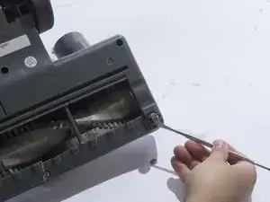
    • Remove the small front wheels with a metal spudger by inserting the metal spudger in front of the wheel and slowly prying up. This will free the wheel and reveal the screw beneath it.

    • Repeat this for the other wheel.

  5. oaD2BLUuvCA6rPWW
    oaD2BLUuvCA6rPWW
    p2ir1yL1wuOemfUW
    • Remove the two 18mm screws with a JIS 1 screwdriver.

  6. IrOsPIoU3iKbPthm
    IrOsPIoU3iKbPthm
    IRMNFxcCKZFqGaOS
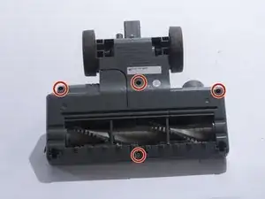
    • Remove the four 18mm screws located on the top corners and the bottom/middle of the vacuum head using a JIS 1 screwdriver.

  7. Wq1My4VORBGeVGDZ
    Wq1My4VORBGeVGDZ
    mDH5cGEJoETL6MYi
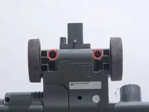
    • Remove the two 18mm screws located on the inside of the large wheels using a JIS 1 screwdriver.

  8. Z4ye12rd4SDmEY33
    Z4ye12rd4SDmEY33
    21jhgcPRRmYmtAXY
    xftShVor2sKTnYaA
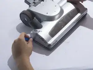
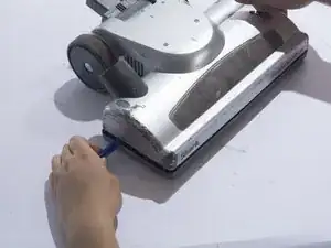
    • Remove the plastic cover by prying the plastic cover up using a plastic opening tool.

    • Prying in multiple locations may be necessary to create separation.

  9. GuCEAuMqOZPM42Cb
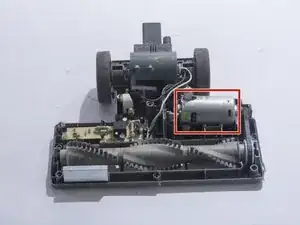
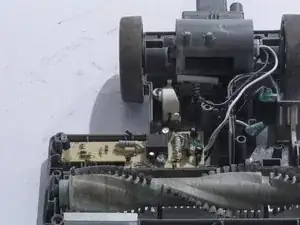
    • Locate the motor on the top right corner of the vacuum head shell.

  10. fUVTXt3bQIe6U3tF
    fUVTXt3bQIe6U3tF
    HmTES4REybXxWGTr
    soI1xSRCLaNlOsT4
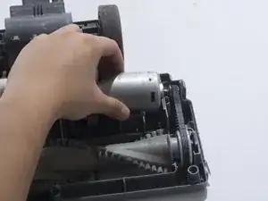
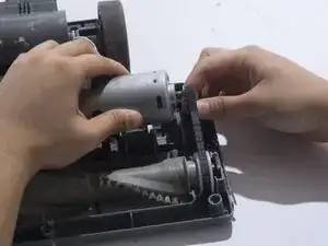
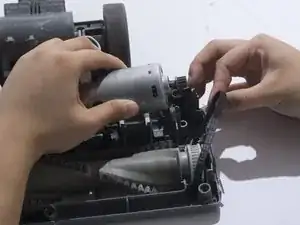
    • Remove the belt from the motor gear by sliding the belt to the right.

  11. ClHavNN2iNZffaKI
    ClHavNN2iNZffaKI
    i1c2TRoVNBsrFmbV
    mjOhEpsBCSyq5OhZ
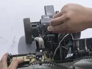
    • Remove the white metal wire connector from the motor.

    • The white cable is positive.

  12. KTVQsQwmw1IPqRTY
    KTVQsQwmw1IPqRTY
    YHNjREBDxUJwWY45
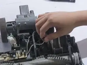
    • Remove the black metal wire connector from the motor.

    • The black cable is negative.

  13. ktD2qMFaKKxfNWQl
    ktD2qMFaKKxfNWQl
    fFbrSmX5v6LEtOsT
    • Remove the two 12mm screws using a JIS 1 screwdriver.

  14. 5SCvnZVGJeMjSxmu
    • Remove the wire housing by removing one 12mm screw using a JIS 1 screwdriver.

  15. CTkPR2wfkZWXNDI6
    CTkPR2wfkZWXNDI6
    sDPuYWFTMHLvvWbT
    • Lift up the wire housing from the plastic base using tweezers.

  16. BUkqEAWAHZdQApky
    BUkqEAWAHZdQApky
    GDO1dRT6BVIWLeft
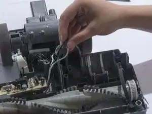
    • Free the black and white cables that were previously attached to the motor from their slot.

  17. ftcrJj44qKMPcATG
    ftcrJj44qKMPcATG
    WQHcQfSNawKHpAJI
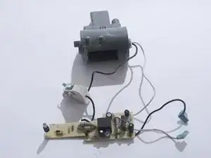
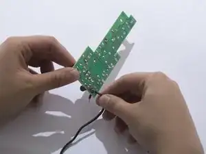
    • Free the motherboard and its connecting parts from the rest of the vacuum.

    • Turn the motherboard upside-down and spread wires out.

  18. KSDugBstykwQFWgv
    KSDugBstykwQFWgv
    bZARgsUEaXMAL3vi
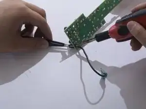
    • Heat the wire connection's solder joint until the joint looks wet and liquidy.

    • While maintaining contact with the solder iron, free the wire end by pulling the wire away from the board with the tweezers.

    • For instructions on how to solder properly please refer to this soldering technique guide. How To Solder and Desolder Connections

    • Remember which cables were soldered onto where. You will have to re-solder the cables back onto the same joint.

    • Solder iron is extremely hot and should be handled with care. Always wear eye protection when soldering.

  19. OZlHrsMtHki4lIwX
    OZlHrsMtHki4lIwX
    DePAbywOYYASdqHo
    UxGSFLTotcaWECcZ
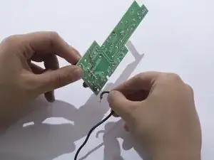
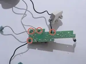
    • Completely free the cable by pulling it out of the board.

    • Repeat for the remaining cables. There are 4 total.

Conclusion

To reassemble your device, follow these instructions in reverse order.
Suzie

Member since: 02/10/17

527 Reputation

0 comments