Introduction

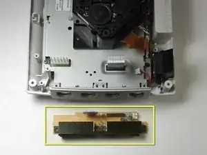
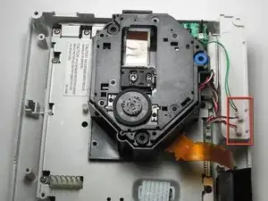
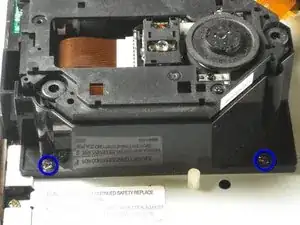
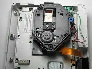
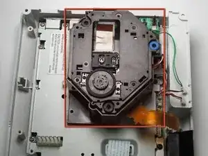
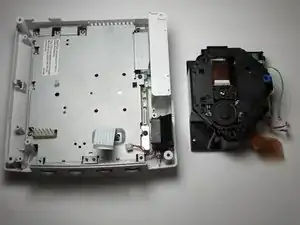
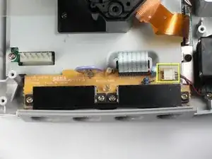
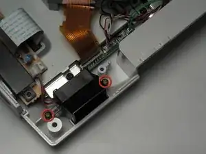
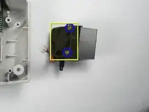
A guide to remove the Logic Board from the Sega Dreamcast.

  1. rdFJlNVwMtT3hJRD
    rdFJlNVwMtT3hJRD
    BGojrPldMPBm4Yew
    • Verify that the console is disconnected from the AC outlet before you begin.

    • Flip the console over on its back.

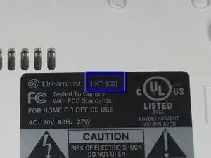
    • Take note of your model number, in case replacement parts are needed.

  2. HDbDfaw3TOGBMCHi
    HDbDfaw3TOGBMCHi
    b12VKhkOV53BrRt3
    ZxvUK2uvuTY4pH1H
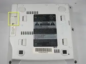
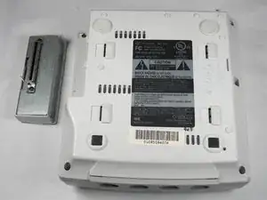
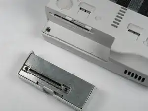
    • Remove the expansion bay by applying pressure to the small clip on the expansion bay while prying it away from the console.

  3. j4mn2GW3UHoTNIAH
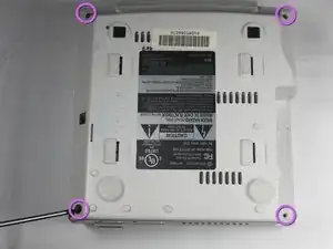
    • Locate and remove all four black 12mm Phillips #02 screws from the underside of the console.

    • Note: Remove the expansion bay to locate the fourth screw

  4. KGQFrciudkmBDQJX
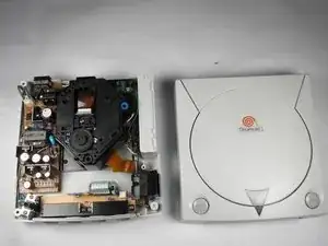
    • Internal components can be loose. Be careful that they do not fall out when removing the cover.

    • Turn the console right side up.

    • Remove the top cover by gently lifting the upper portion of the console.

  5. jyBUYSfshPqZkPFi
    jyBUYSfshPqZkPFi
    CFapUZAT5FMHNsIG
    • Verify that the console is disconnected from the AC outlet before you begin. If you have just powered off the system, give the capacitors a few minutes to discharge before you begin working.

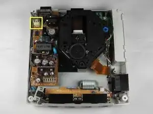
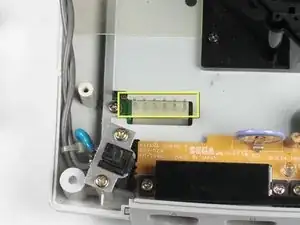
    • Remove the white female pin header by clamping the clip and pulling it up gently from the power board.

  6. VNFffdBYp2eUXyHN
    • Remove the two 10mm Philips #02 screws that are fastened to the power block.

  7. XgMCYlIimpObCCZU
    XgMCYlIimpObCCZU
    OaYoOp12FpdttLGO
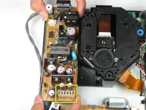
    • Do not bend the male pin header between the mounted head when you remove the power supply from the chassis.

    • Remove the power board by using both hands to gently lift the power board away from the console.

  8. l3TNMLFWvv3Yd6i5
    • Remove the clear plastic film that is tucked between the power supply and the chassis.

  9. sTkunRJrnS2ghCtU
    sTkunRJrnS2ghCtU
    spGdacnu5ME4BPv2
    • Be gentle with the white controller cable as it can be a bit fragile.

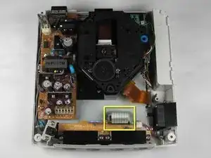
    • Disconnect the white controller cable by gently pulling the the cable while wiggling it back and forth until it detaches from the controller board.

    Note that on some Dreamcasts the power board (on the left) overhangs slightly over the controller board, meaning one must also remove the power board at this stage. This is relatively straightforward, fortunately. Remove a screw each at the top left of the power board and at the bottom left of the power board, remove the white clip at the top left, pop out the white clip on the left of the power board and lift the power board out from the front where you have the white block containing eight pins that connect the power board to the sub board. Then proceed per the rest of this guide. Hope this helps.

    JP Asher -

  10. arRQupUNRImkrXRS
    arRQupUNRImkrXRS
    dKVv1VCXn1jmFMCf
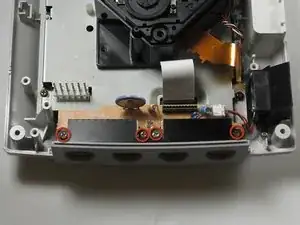
    • Remove the four 14mm Philips #02 screws located on the controller board.

  11. ZODCHfjIJ1WlPSjb
    ZODCHfjIJ1WlPSjb
    LPN1ltPGsaAZNGWt
    • Disconnect the white fan header from the controller port.

    Perhaps list the battery type an battery holders that allow for easy replacement in the future?

    Brett Kampf -

  12. 35Bjo2fcSKkqAqSa
    35Bjo2fcSKkqAqSa
    LiVmAEBfYsNHGqwC
    • Remove the controller board by lifting it up from the controller port.

  13. UqnkwsEhKXEaDccZ
    UqnkwsEhKXEaDccZ
    WCnVuvsLWJUYqnId
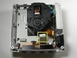
    • Detach the orange cable by giving it a gentle pull while wiggling the cable back and forth until it loosens from the logic board.

  14. ms2ncVxe2h4NQsNb
    ms2ncVxe2h4NQsNb
    TUZoEl54cKfFU6EM
    • Detach the cables by gently pulling the three GD-ROM cables to remove them from the logic board.

  15. P6mDmXfpjHs3QMpt
    P6mDmXfpjHs3QMpt
    noSoOLAmlYwJyxMN
    • Remove the two black 12mm Philips #02 screws located on the left side of the GD-ROM bracket.

    • The console is rotated 90 degrees counter-clockwise in the first photo. The second photo depicts the normal position.

  16. S65eQ5lEBJeGT5aj
    S65eQ5lEBJeGT5aj
    rFmcoWxRScGUCISp
    • When lifting the GD-ROM, be careful that the top half of the casing does not detached from its base.

    • Remove the GD-ROM by gently lifting it from its base.

  17. 1wIiMZDBQZFPTkcv
    • Remove the white fan header by gently pulling it away from from the controller port.

    • The white fan header may already be detached if you have completed the Controller Port Disassembly Guide.

  18. rAFBm1RFSarPyiKA
    • Remove the two 8.5mm Philips #00 screws from the fan bracket.

  19. 55CdJtvg1vQvIGFS
    55CdJtvg1vQvIGFS
    yRF1Wp3LH3JLrCCL
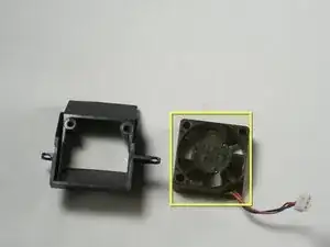
    • Remove the two 17.5mm Philips #00 screws from the fan bracket.

    • Remove the fan from the bracket.

  20. hwg2nPTW3CYdOXsT
    hwg2nPTW3CYdOXsT
    bKrKp5BgWvnyu3Gd
    d1Jy41rOAtIj6mVN
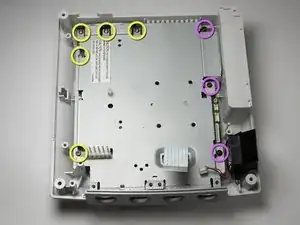
    • Remove the five 10mm Philips #02 screws from left side of the logic board cover.

    • Remove the three black 12mm Philips #02 screws from the right side of the logic board cover.

  21. hnhU6WKGFT5I4YSM
    hnhU6WKGFT5I4YSM
    TcTKkJE34PTkFxqH
    iEpXeKTAmdIZRVBT
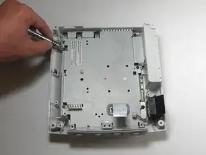
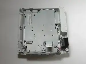
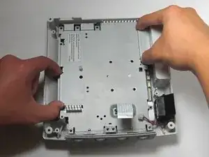
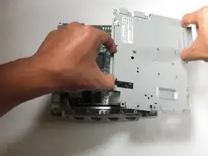
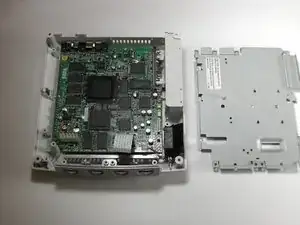
    • Lift the metal cover from the console.

  22. ahtsoP1WeNBoMAsu
    ahtsoP1WeNBoMAsu
    WfYjUylJZ6N64Oay
    • Before handing the logic board, you may want to use a grounding strap to protect the device from static charge. If you do not have a grounding strip, you may ground yourself by touching a large metallic object.

    • Remove the logic board and set the logic board on an anti-static surface.

Conclusion

To reassemble your device, follow these instructions in reverse order.

wkwong

Member since: 14/11/09

517 Reputation

One comment

helpful but my dreamcast had a different logic board and as well as fan and gd-rom so keep that in mind if u see something different in your unit
Nickolas Wilcox -