Introduction
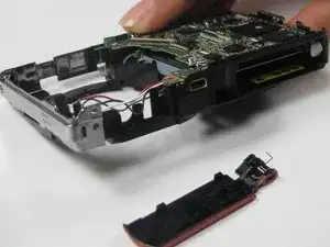
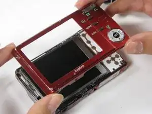
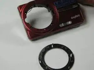
This guide includes instructions for removing the main board.
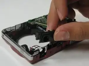
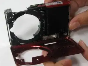
The main board consists of the motherboard, plastic frame, flash capacitor, and battery tray. The motherboard cannot be separated from the main board without breaking either of the pieces. Luckily, main boards are sold as one unit.
Tools
-
-
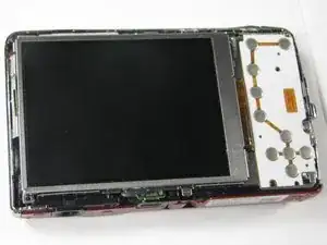
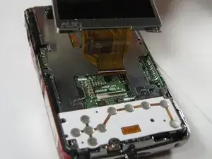
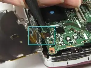
Gently lift up on the left side of the LCD and slowly pull it to the left side of the camera but do not remove entirely, there is a ribbon connector.
-
-
-
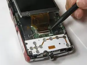
To clear the ribbon connection underneath the screen, lift up the black ribbon gate with the spudger.
-
Gently lift ribbon out of the gate and set screen aside.
-
-
-
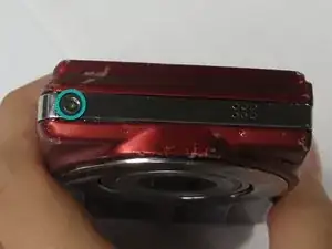
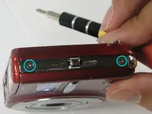
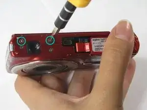
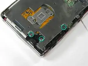
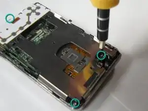
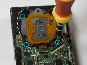
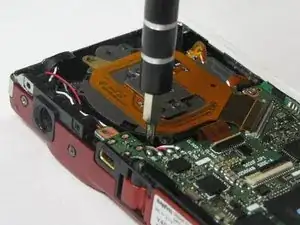
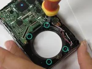
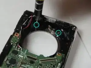
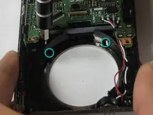
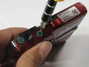
There are five screws of three different sizes which need removal.
-
One 4.5mm screw
-
Four 3.5mm screws, one on the button side
-
One 5.5mm screws
-
-
-
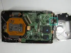
Slowly lift metal tray to the right.
-
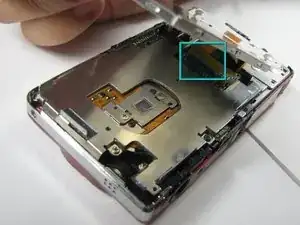
Remove ribbon cable by using the spudger to lift up the black ribbon gate to release the ribbon
-
-
-
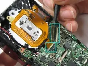
Disconnect the two ribbon cables from the lens unit by using the spudger to lift the ribbon gates.
-
-
-
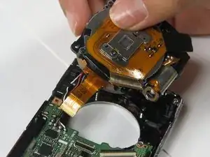
Lift the lens unit free of the camera. A spudger can be used to separate the lens unit if necessary.
-
-
-
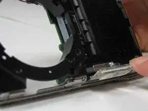
Remove the flash lens using the spudger or a finger.
-
It will be attached by a piece of tape, peel the lens off of that piece of tape without removing the tape.
-
-
-
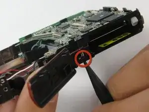
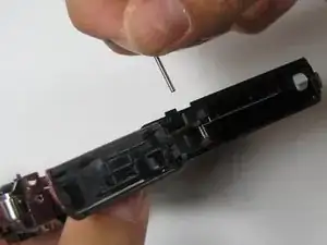
Push out pin that holds the door hinge together
-
Pull out the pin. Be careful to keep track of the spring and black spacer.
-
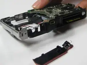
Set the battery door aside
-
To reassemble your device, follow these instructions in reverse order.
