Introduction
This is a prerequisite guide to take off the back cover assembly.
-
-
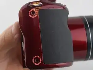
Remove the 7 screws on the outside of the camera
-
Two 5 mm PH000 screws on the right side of the camera body
-
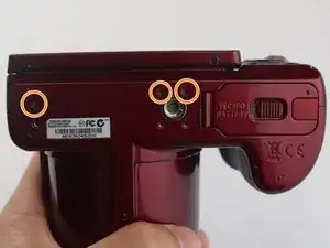
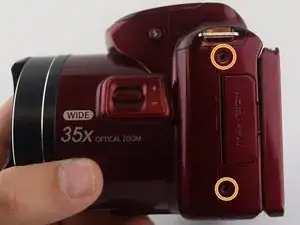
Four 3mm PH000 screws on the bottom and the left side of the camera body.
-
Use the plastic spundger to push the back casing out. Start from the right side and work your way clockwise around the case.
-
-
-
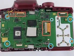
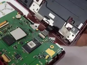
Disconnect the set of wires from the back casing to the motherboard. Do this by using the plastic spundger to flip the black tab up and the wires will pull out.
-
Unscrew the four 3 mm and two silver 1 mm PH000 screw from the green logic board
-
Conclusion
To reassemble your device, follow these instructions in reverse order.