Introduction

  1. MTTfykDvMqSbmg4o
    MTTfykDvMqSbmg4o
    jW6tNuSU22FQdZgX
    1DOMXLmYXMD3gfYL
    • Remove these screws from the camera using a phillips head screwdriver.

  2. A2Yary4gi2WgK2Vy
    • Lay the camera down on the table and remove the metal shell from the front.

  3. 5AIjF2GxENOioVFK
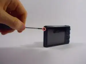
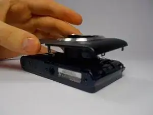
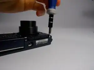
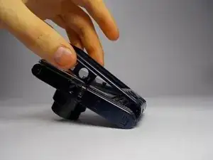
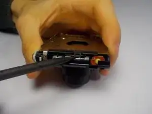
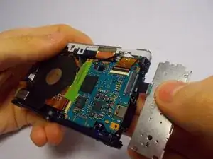
    • Wedge a spudger/flathead screwdriver inside of the shell where the screws were to pry the shell off of the back.

  4. rMIWKptAOhEGpNYB
    • Remove the shell the from the back of the camera.

  5. IOFXDGGBQTXFcpei
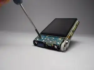
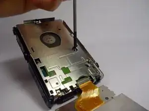
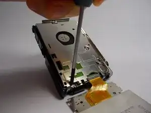
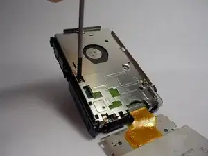
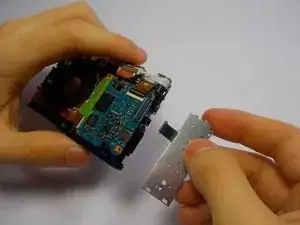
    • Remove the Phillips head screw from the rear panel control board to reveal the LCD's connection to the motherboard.

  6. YYsBdwyeiWLnoKjV
    YYsBdwyeiWLnoKjV
    eoBn5WG66aJxUaGp
    F26WBQw1YWQKLlTi
    • Remove the Phillips head screws from the metal back plate.

  7. HCWPoLrQcRQi1PZK
    • Use the spudger to life the tab on the side of the metal plate.

  8. PnYhItiXl2o3tDAp
    PnYhItiXl2o3tDAp
    J3gHJCWOFUMaF2SS
    • Pull gently on the control panel to remove it from the motherboard.

Conclusion

To reassemble your device, follow these instructions in reverse order.

Matthew Eaton

Member since: 29/03/15

107 Reputation

0 comments