Introduction
This guide will show users how to remove and replace the lens unit if the unit is malfunctioning or damaged.
-
-
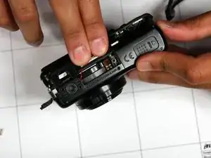
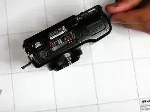
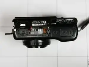
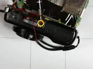
Rotate camera such that battery door is facing upwards
-
Squeeze area where fingers are located with thumb and remove outside shell.
-
-
-
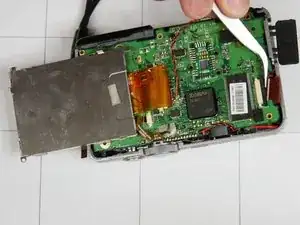
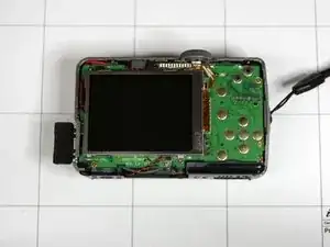
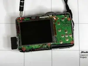
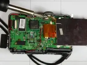
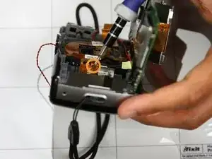
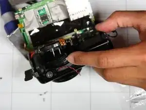
After removing you see a few wires and a screen placed on top of the circuit board looking similar to the first picture. If you don't, you might have not taken apart the wrong camera, yikes!
-
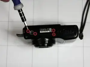
The second picture outlines where you can locate all the surface screws. Note that these will not be the only screws needed to be taken off to remove the circuit board.
-
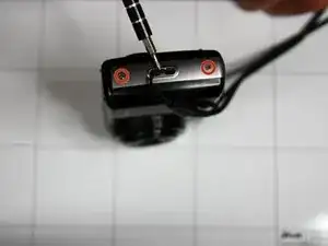
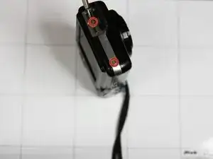
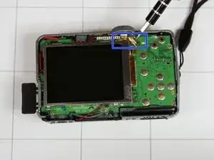
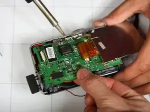
As shown in the third picture be careful when removing the screw hidden behind the circuit.
-
-
-
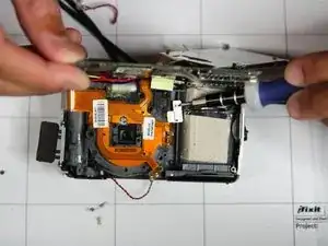
After removing two screws holding screen down flip screen over gently.
-
Remove three screws underneath screen as shown in pictures
-
-
-
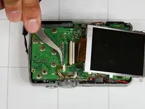
Using tweezers, pinch white portion of circuit as shown in picture and twist upwards. This should loosen the circuit itself.
-
Using tweezers, gently remove circuit from white plastic attachment.
-
Flip screen over and remove top most circuit closest to power button using same method.
-
-
-
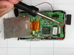
Using a soldering iron, remove solder from each circled location in each image to remove corresponding wires
-
-
-
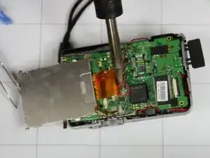
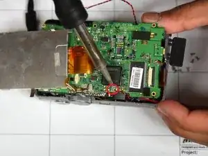
Using soldering iron, melt away solder and warm up metal located at top of circuit board as shown in picture
-
Repeat step two to three times until board feels flexible to bend
-
-
-
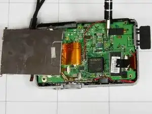
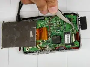
Slowly bend circuit board upwards (towards power button) until at 90 degree angle with remaining part of camera.
-
-
-
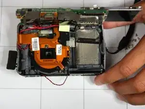
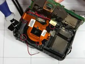
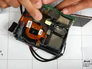
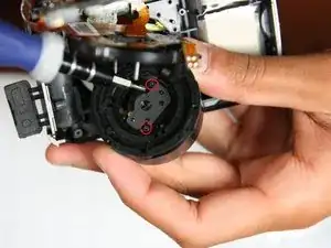
Remove three interior screws as noted in the first picture.
-
Remove screwed attached to orange circuit ribbon as shown in second picture.
-
Remove third screw attached to orange circuit ribbon as shown in third picture.
-
-
-
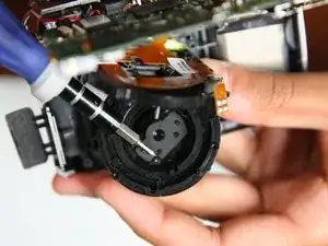
Using screwdriver, remove silver metal piece located in center of camera.
-
Using tweezers, gently remove orange circuit from lens. This step is tricky as the orange circuit is very securely placed in the lens.
-
After the removal of the silver piece and orange circuit remove black circle from center of camera. This is the lens
-
Gently remove top portion of lens as shown in the third picture.
-
-
-
Remove two screws attached to internal part of lens using screwdriver
-
Using tweezers to remove thin black layer to reveal lens.
-

To reassemble your device we have provided pictures working backwards.