Introduction

Prerequisite Only

  1. GUj6mCo6yWsxTFn2
    GUj6mCo6yWsxTFn2
    DvaOwYjSF1DOTZeD
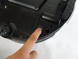
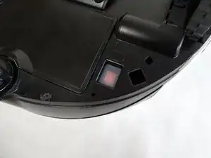
    • Turn off the emergency switch located at the bottom right of the POWERbot.

  2. mE3suRcpXbVXIEoJ
    mE3suRcpXbVXIEoJ
    4BlVlpqonOdltfja
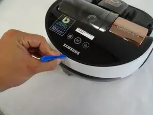
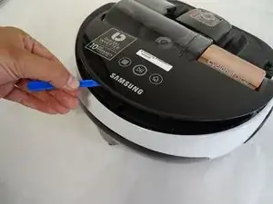
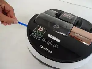
    • Insert the plastic opening tool under the black cover, near the Samsung logo on the back of the device, and partially pry open.

  3. 2VNEyXfOxkf5v2Py
    2VNEyXfOxkf5v2Py
    fcQAfgRWYNqGOScD
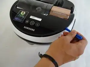
    • Slide the plastic opening tool to the left, remaining under the black cover, until two left side pins have been detached. Then slide the plastic opening tool to the right until two right side pins have been detached.

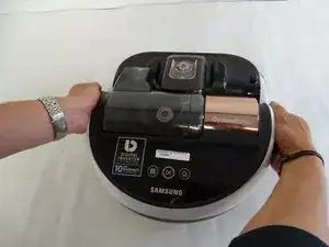
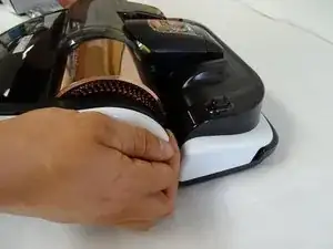
    • Grab the two clips near the front of the black cover, on in front of each wheel. Pull the clips away from the wheels.

    I needed to replace the left drive wheel on a SR20J9250U model. It is largely the same and many parts have VR9000H stamped on them. I will add any differences as I see them.

    For this step, there are three clips plus the clip in front of the wheel on each side. First clip is approx 6 cm from the centre at the back. Next is approx 11cm from the first clip and the third is 11 cm from the second clip (almost above the wheel). Then there is the clip in front of each wheel that you can see.

    Matt -

  4. xIMeYCUmsJ14rG5J
    xIMeYCUmsJ14rG5J
    6klfPLuYITumm2Oc
    w6EfbcdSc2OXcDLf
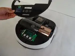
    • Remove the black cover.

  5. wVYNjfLBJZ5kZEZt
    wVYNjfLBJZ5kZEZt
    MXZnY4GPTSAnkHDZ
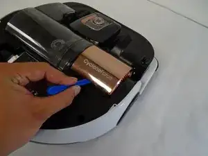
    • Insert the plastic opening tool under copper-colored cover, under the words "CycloneForce," and pry open, applying a small rotation, until the two pins are released .

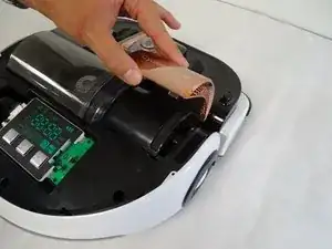
    • Grab the underside of the cover and lift upwards while pushing forward until the cover pops off.

  6. 6GomGSOobbRhsKkM
    6GomGSOobbRhsKkM
    FTZwjpvOYfNqZWmX
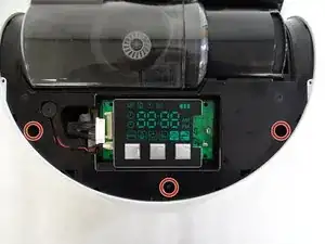
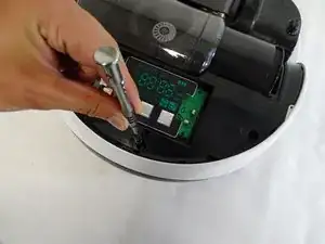
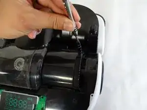
    • Remove the three 6mm Phillips #1 screws in the holes near the back of the device.

    On my model SR20J9250J there is a forth screw on the right hand side I front of the vacuum motor that needs to be removed to lift the body off in step 10.

    Matt -

    Whoops, this is step 7. Read further next time.

    Matt -

  7. 1gZuXJYfDLEWNLHk
    1gZuXJYfDLEWNLHk
    MPOWlVVODTsIAZDF
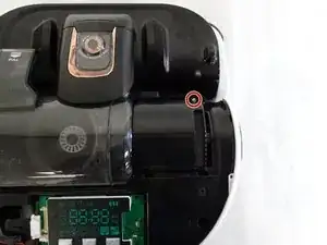
    • Remove the 6mm Phillips #1 screw in the hole that was under the copper-colored vacuum cover.

  8. LNjD4UM4C64Wk2Je
    LNjD4UM4C64Wk2Je
    cXyXgOtSJEdMHbge
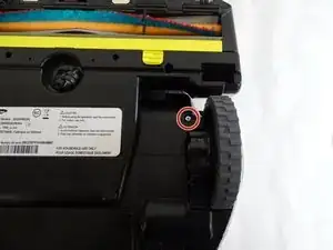
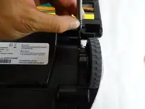
    • Flip the device over and remove the 6mm Phillips #1 screw in front of the left (from this perspective, right) wheel.

  9. C1JIMkkmF1EBQTPE
    C1JIMkkmF1EBQTPE
    4ETAQWmi1KNQXfIP
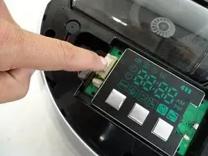
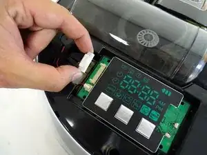
    • Detach the wider circuit connector by pressing down gently on the left end of the clip and pulling the connector out.

    • Pull the connector out by the top and bottom of the white piece and not by the wires.

  10. ZmySkRyRGvwGQSPp
    ZmySkRyRGvwGQSPp
    qTPTounODwtegiBL
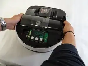
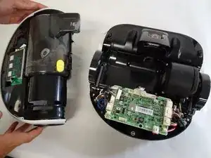
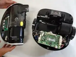
    • Remove the top chassis from the POWERbot by grabbing the wheel covers and lifting upwards.

    Remove screw on bottom of wheel

    Doris Emrich -

Conclusion

To reassemble your device, follow these instructions in reverse order.
Kyle Chin

Member since: 24/04/17

1919 Reputation

0 comments