Introduction
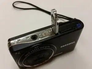
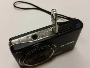
This guide allows you to replace the lens on your Samsung Pl200 camera. To complete this guide you will need a #000 Phillips Screwdriver, a Plastic Opening Tool, and a set of Tweezers.
-
-
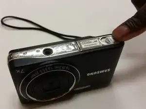
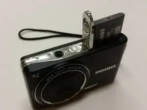
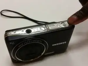
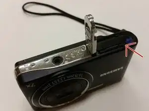
Flip Samsung PL200 over to access battery/SD card compartment on the bottom. There is a sliding release button (labeled 'OPEN') that can be slid sideways to open the battery/SD card compartment.
-
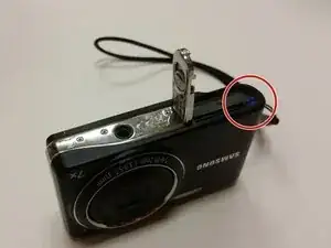
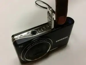
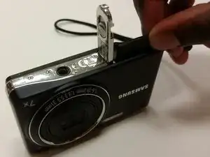
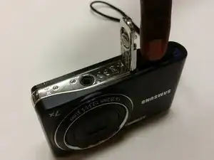
Slide this button in the direction that the arrow is pointing to release and open the spring loaded battery/SD card compartment door. Once opened, the battery should be visible.
-
-
-
Once the battery/SD card compartment is opened, in order to remove the battery, you must push the small blue release button.
-
This will release the spring loaded battery.
-
Use your fingers to remove the old battery.
-
-
-
Insert the new battery into the battery slot.
-
Push it down with your finger until the blue release switch re-engages over top of the battery.
-
Close the battery/SD card compartment.
-
-
-
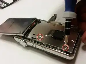
Remove the six 3 mm external screws from the camera base using the Phillips #000 screwdriver.
-
-
-
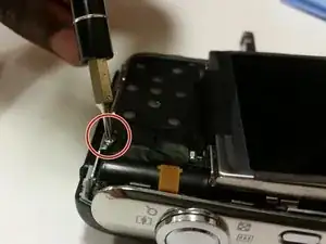
Remove the 3 mm screw holding the circuit board.
-
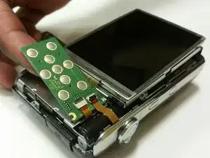
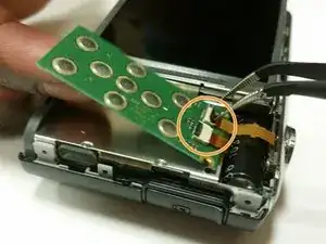
Use a pair of tweezers to detach the two ribbon cables connecting the circuit board to the camera.
-
Remove the circuit board.
-
-
-
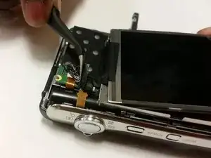
Flip the LCD screen forward and remove the two 3 mm screws holding the metal midframe using a Phillips #000 screwdriver.
-
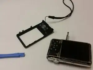
Remove the midframe using an opening tool.
-
-
-
Lift the black strip and the ribbon will easily come out.
-
After doing this, the LCD screen will be separated from the camera.
-
-
-
Flip Samsung PL200 over to access battery/SD card compartment on the bottom. There is a sliding release button (labeled 'OPEN') that can be slid sideways to open the battery/SD card compartment.
-
Slide this button in the direction that the arrow is pointing to release and open the spring loaded battery/sd compartment door.
-
Once opened, the SD card should be visible.
-
-
-
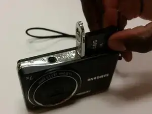
Once the battery/SD card compartment is opened, simply push the SD card down to activate the spring loaded ejector.
-
This will cause the SD card to raise up enough to allow you to grab it with your fingers.
-
Use your fingers to remove the old SD card.
-
-
-
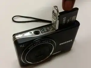
Insert the new SD card into the SD card slot.
-
Make sure to push it down all the way until it clicks and remains flush with battery.
-
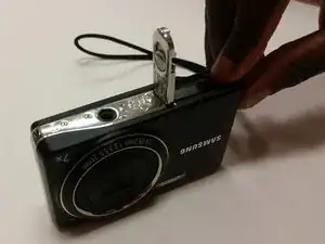
Close the battery/SD card compartment.
-
-
-
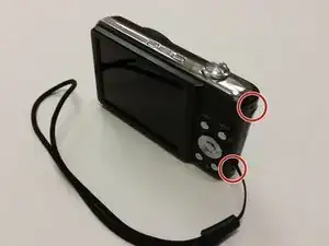
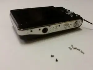
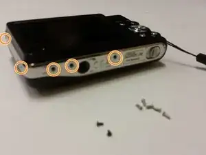
Remove the two black 3 mm screws from the right side of the camera using a Phillips #000 screwdriver.
-
Remove the five silver 3 mm screws from the camera's side and bottom using a Phillips #000 screwdriver.
-
-
-
Remove the single 3 mm screw securing the circuit board with a Phillips #000 screwdriver.
-
Remove any leftover tape on the circuit board and screen.
-
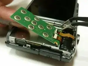
Unplug and remove the wires from the circuit board using a set of tweezers.
-
-
-
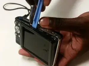
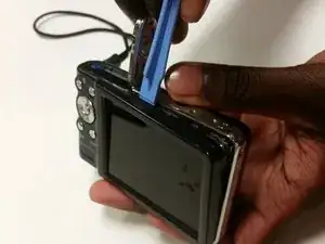
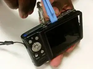
Flip the LCD screen forward and out to the side.
-
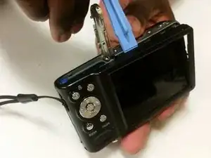
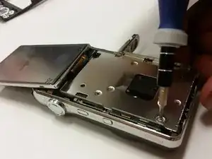
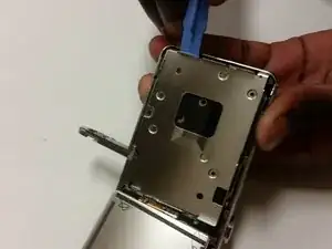
Use a Phillips #000 screwdriver to remove the two 3 mm screws beneath the LCD screen.
-
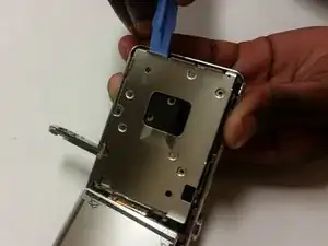
Remove the metal brace using the Plastic Opening Tool.
-
-
-
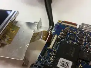
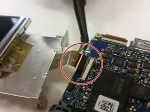
Flip the ZIF connector's locking bar vertically, then gently remove the ribbon cable.
-
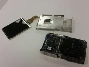
Remove the screen.
-
-
-
Set the screen and metal brace aside.
-
Open the camera’s battery compartment on the bottom part of the camera.
-
-
-
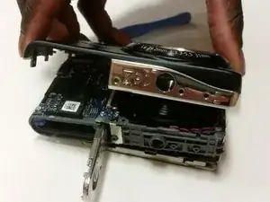
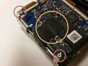
Remove the two 3 mm corner screws that secure the motherboard, with a Phillips #000 screwdriver.
-
Remove any leftover tape that may still be on the motherboard.
-
-
-
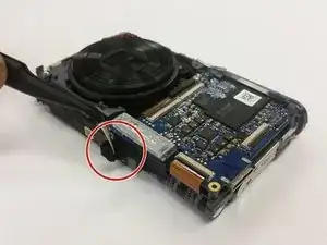
Use tweezers to remove the tape from the bottom of the camera.
-
Then use the tweezers to disconnect the lens unit cord at the bottom of the camera from the motherboard.
-
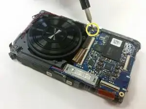
Remove the last 3 mm screw securing the motherboard with a Phillips #00 screwdriver.
-
-
-
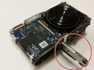
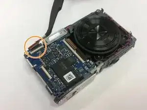
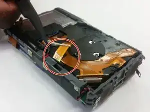
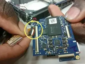
Use tweezers to unplug the small lens unit cord from the camera frame on the backside of the camera.
-
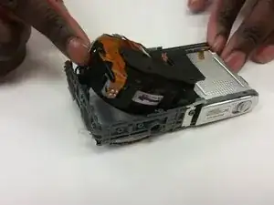
Gently lift the lens unit from the frame.
-
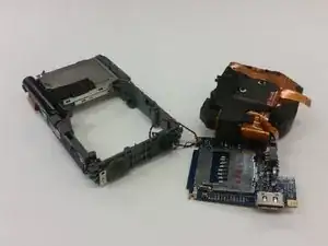
Separate the lens unit, motherboard, and camera.
-
-
-
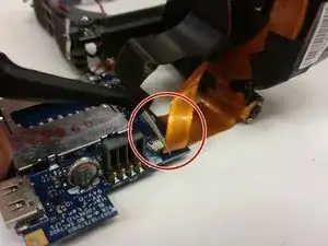
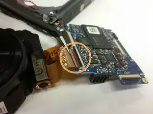
Use tweezers to disconnect the small ribbon cable from the motherboard.
-
Then use the tweezers to remove the first large lens unit ribbon cable from the motherboard.
-
Finally, use the tweezers to remove the second large lens unit ribbon cable from the motherboard.
-
-
-
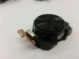
You have now separated the lens unit. Replace it with a functional lens unit at this stage, and reassemble the device.
-


To reassemble your device, follow these instructions in reverse order.