Introduction
A commented How To to disassamble the Samsung NaviBot SR8981 (VCR8981L3B-XEG) to its parts.
The How To in the Answer of szantaiimre on the following page helped me a lot, whith slight adjustments (same Manufacturer, other Modell, but near enough)!
-
-
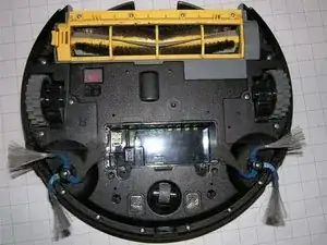
Screw on the battery compartment at the green marked points and open the lid.
-
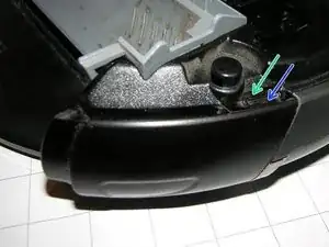
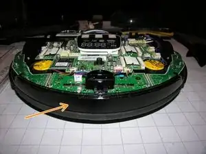
The blue arrow marks the connection between the battery and the housing. Once this is solved, the battery can be removed from the device.
-
-
-
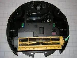
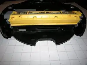
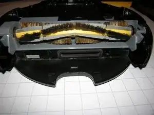
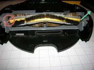
The brush can be easily lifted out of the warehouse on the right and then removed to the right.
-
-
-
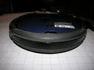
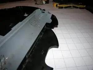
The first picture shows the side view.
-
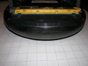
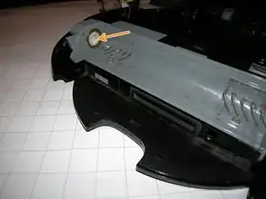
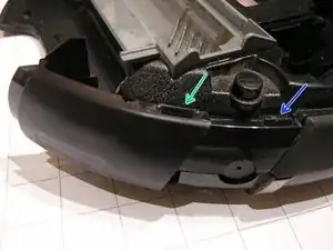
Second picture: The plastic bracket (green arrow) of the side part must be carefully levered over the plastic nose (blue arrow). Subsequently, the side part can be pulled backwards.
-
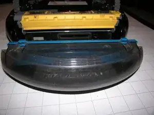
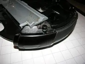
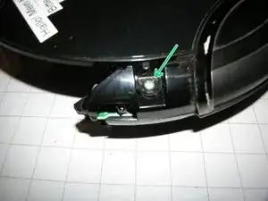
Third picture: The side panel has been pulled back, now the plastic bracket (green arrow) and the plastic nose (blue arrow) are clearly visible.
-
-
-
Loosen screws on the left (first picture) and on the right
-
Second picture: carefully loosen the plastic claw and pry off the cover plate.
-
Third picture: the NaviBot without cover plate
-
-
-
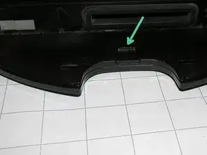
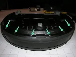
To disassemble the front sensor cover, the six screws on the bottom (second picture) must be removed.
-
-
-
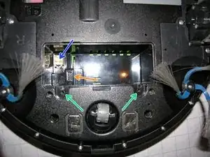
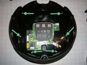
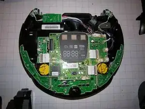
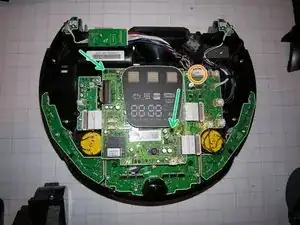
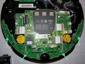
Remove the screws on the green arrows.
-
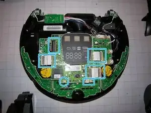
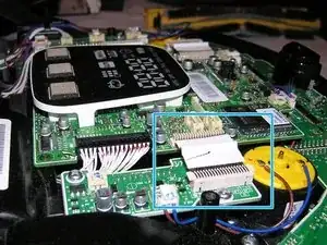
Release the plug connections (Fig. 2). Caution: especially the rigid cable connections (Figure 3) are a bit difficult to open and can be damaged without the proper caution.
-
-
-
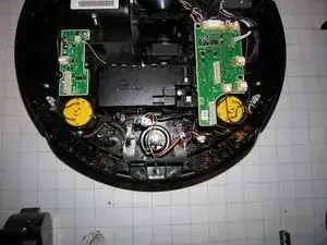
Once the four front screws are loosened, the front tripartite sensor board can also be removed.
-

Follow the instructions in reverse, to reassamble the Device.