Introduction

Navigation buttons are used to operate the camera and its various settings and features.

  1. IGdQZS1QJkyRioAW
    IGdQZS1QJkyRioAW
    JLeR4pTIJlr2yaoO
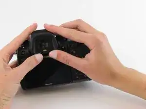
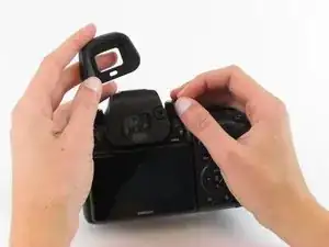
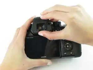
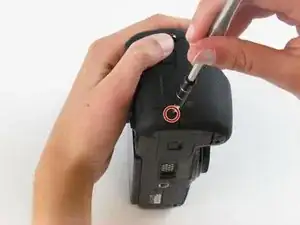
    • Push the rubber viewfinder grip upward.

  2. eGdBvIaiWOSJntxW
    eGdBvIaiWOSJntxW
    kFWYU3RV1IXovxIV
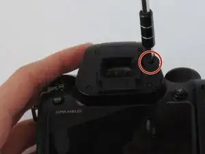
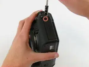
    • Use the Phillips #00 screwdriver to remove one 6.4 mm screw in the center of the dial.

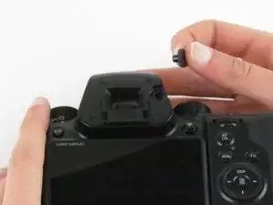
    • Remove the dial by lifting upward with your fingers.

  3. RvfS1P2RGWDCOypj
    RvfS1P2RGWDCOypj
    hBa3piweB6QVKCmN
    tQDYyH2YXNWnDU3X
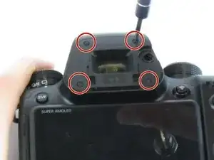
    • Use the Phillips #00 screwdriver to remove the four 5.5 mm screws surrounding the viewfinder.

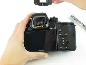
    • Use your fingers to lift the plastic viewfinder cover upward.

  4. LNjceZHlWZfL12hT
    LNjceZHlWZfL12hT
    aNWWWQQEhUmVt5fl
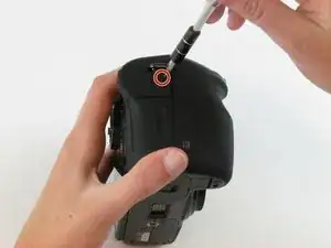
    • Use the Phillips #00 screwdriver to remove the two 5.5 mm screws from the right side of the camera above the SD card port.

  5. ZfYWL2iCFNMriyxg
    • Use the Phillips #00 screwdriver to remove one 5.5 mm screw on the left, above the HDMI port.

  6. j5tgvVQLmQ2VYaZv
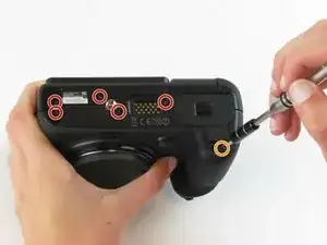
    • Use the Phillips #00 screwdriver to remove the five 5.5 mm screws from the bottom, near the battery compartment.

    • Use the Phillips #00 screwdriver to remove one 3.8 mm screw from the bottom of the hand grip, below the battery compartmen.

  7. rPQiYRuoBe1HBP3v
    rPQiYRuoBe1HBP3v
    fAfWSqbp2j3qTVQv
    jAZZmNcUKwIwGfrL
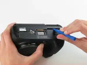
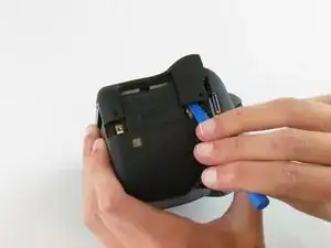
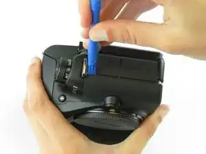
    • Use a plastic opening tool to separate the back cover from the front cover.

    • Pry the back cover in this order: bottom, right side, left side.

  8. B6naUETNiVJdYOCW
    B6naUETNiVJdYOCW
    oqArXtXFGNAjphHA
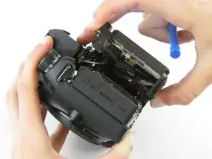
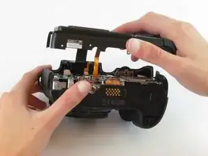
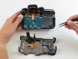
    • Use your fingers to pull the back cover away from the front cover.

    • Do not completely separate the back cover from the front cover as two cables hold these components together.

  9. 2HR6BWnVsdZZvBjq
    2HR6BWnVsdZZvBjq
    OlNJEt6IkckntOCK
    YG146ZGfNdhcMvwI
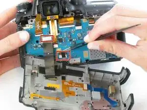
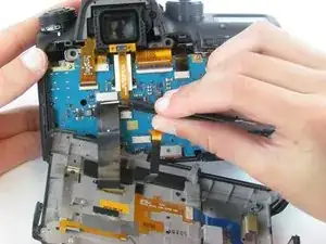
    • Use tweezers to pull the two ribbon cables horizontally out of their clips.

  10. ltjmQpXnbRC5PtWu
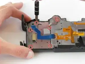
    • Use the Phillips #00 screwdriver to remove the six screws (three silver 3.5 mm screws and three black 4.2 mm screws).

  11. iLRY5AgHBSjBVaiK
    • Use the tweezers to pull the blue ribbon cable horizontally out of its clip.

  12. eBuQ4PnATOYDJ2rN
    eBuQ4PnATOYDJ2rN
    pnBYqnDyJJBtd3k3
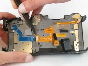
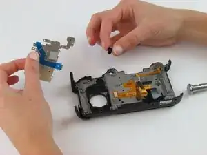
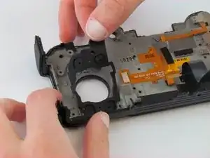
    • Use your fingers to remove the metal piece with the blue ribbon cable and the rubber buttons lying underneath.

Conclusion

To reassemble your device, follow these instructions in reverse order.
Hannah Patrick

Member since: 24/02/16

891 Reputation

0 comments