Introduction

For the user to remove the camera lens of the Samsung HMX-W200, they will first need to remove the components protecting the lens.

  1. QYAPnfNEvKb1LrTV
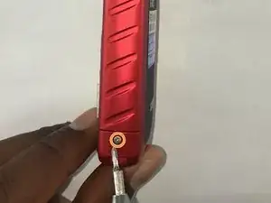
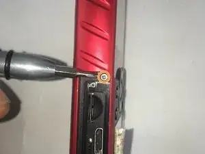
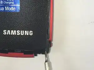
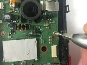
    • Remove the 5.00mm screw on the right of the LCD display towards the bottom of the device by using a Phillips #00 screwdriver.

    You also have to remove the screws at the bottom of the threaded stand mount hole, and inside the USB cover.

    Deen Hubin -

  2. aDHBBbVwSiVgLMqJ
    aDHBBbVwSiVgLMqJ
    ZtgEBoGPTCtcMJUd
    upPeWbNGkYRldUhE
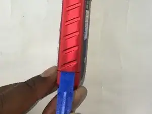
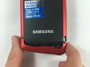
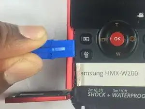
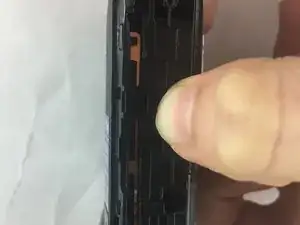
    • Use the plastic opening tool to separate and remove the bottom red casing. Do this by, pushing the tool into the seam and prying up the red casing as you move along the edges.

    • Make sure to separate all the corners before removing the red casing.

  3. qimSZIDWFtUVa62O
    qimSZIDWFtUVa62O
    TDfiUWptwhQxLCsn
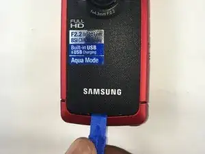
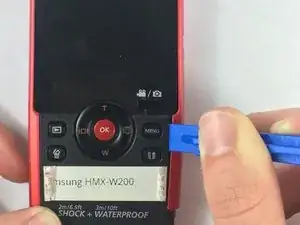
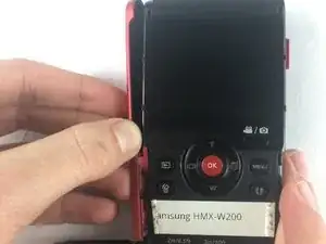
    • Using the plastic opening tool, separate and pull away the red casing on the right of the LCD screen.

    • Make sure to separate all the corners before removing the red casing.

    Also, remove the screw next to the SD card port before proceeding.

    Deen Hubin -

  4. LWZyrk3HkTJaCnyd
    LWZyrk3HkTJaCnyd
    NvFcwXu55IBKmdML
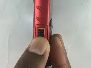
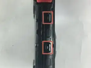
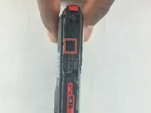
    • To access the HDMI slot, move slider towards the bottom of the casing on the other side of the camcorder. The lid casing will lift up upon doing so.

    • After accessing the HDMI slot you will find a 5.00mm screw. Using a Phillips #00 screwdriver, remove the screw.

  5. yDy4apJjnDYUWESe
    yDy4apJjnDYUWESe
    BUCMfhv4Gm5PAYkj
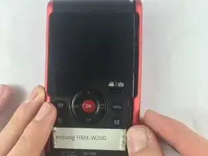
    • Using the plastic opening tool, separate and pull away the red casing to the left of the LCD screen.

    • Make sure to separate all the corners before removing the red casing.

  6. d64WmZGQaKnLuUHE
    d64WmZGQaKnLuUHE
    WZGxyhrgOcROWGGT
    • Remove the six 5.00mm screws by using a Phillips #00 screwdriver.

  7. tT4wC6nPLEJXrOQN
    tT4wC6nPLEJXrOQN
    AEFIEhiAIhAXdxiq
    FLsPoFERbsZdnC6u
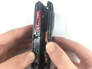
    • Lift the two plastic tabs on the left side of the LCD screen and the single one on the right side on the black casing to open the device.

  8. SdG1Gw1gwc5Vvh33
    • Separate the front and back casing.

  9. cgXqE2oXETCiQ4Mn
    • Once inside the device, find the half that contains the motherboard of the device.

  10. lMnhf22eS6phSyDj
    • Use precision tweezers to gently pull out the USB connection from the motherboard.

  11. FQJh423fXtruW32x
    FQJh423fXtruW32x
    eiL54NmKfGolNBi2
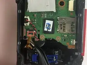
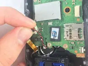
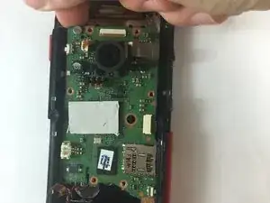
    • Remove the audio connector from the motherboard (red and black cables).

    • Using the plastic opening tool, lift the connectors from all sides before pulling it with your fingers.

    • Do not pull off the connectors by the cables. This could damage the connection from the speaker to the motherboard.

  12. 2JtiEP6eQKgLf1nD
    2JtiEP6eQKgLf1nD
    xFSoKSbQQs1SMVRA
    • Use precision tweezers to remove the connector joining the LCD and the motherboard.

  13. tFeCFrgUHdmywfNO
    tFeCFrgUHdmywfNO
    DtTJ3bDV3FK2sdsd
    • Remove the six 2.00mm screws with Phillips #00 screwdriver.

  14. ZFC61Wi4mapweDMY
    ZFC61Wi4mapweDMY
    LXmVxEgkDYYKGwxX
    NctQAqClorvQrHq4
    • Lift motherboard from top left side and pull away gently.

  15. KM5OScIoL6W3EBrM
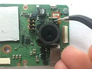
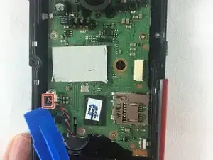
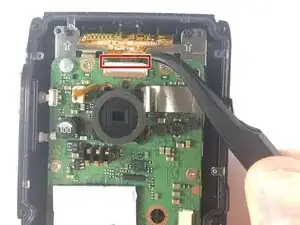
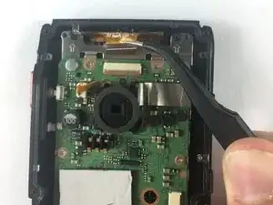
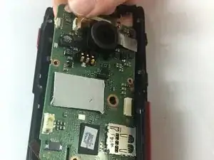
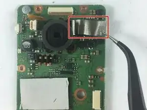
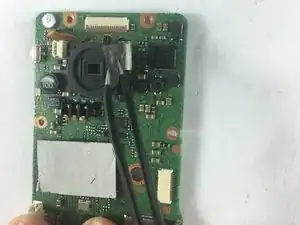
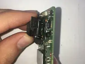
    • Use the precision tweezers, to gently pull and remove the connector connecting lens and motherboard.

  16. Dy2uaKtd1BVJCSa1
    Dy2uaKtd1BVJCSa1
    rqoucEyupktKvswW
    • Using the precision tweezers, lift silver heat sync tape from motherboard.

  17. jhHyZVJEh2XyyogD
    jhHyZVJEh2XyyogD
    BQJtgoaj1JARRGxA
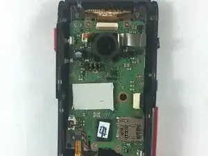
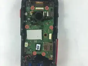
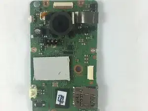
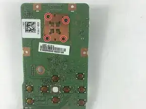
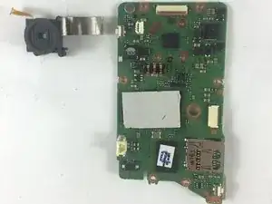
    • Turn the motherboard over.

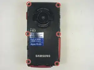
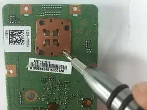
    • Use Phillips #00 screwdriver to unscrew four 4mm screws holding the camera lens to the motherboard.

  18. SxrIv1epyJHbaVHO
    SxrIv1epyJHbaVHO
    CkUBf6WYHekVQZGW
    • Gently grab the lens with your fingers and pull it away from the motherboard.

    • Camera lens should easily come off the motherboard when the last screw is loose.

Conclusion

To reassemble your device, follow these instructions in reverse order.

Haya Barakat

Member since: 04/10/16

521 Reputation

0 comments