Introduction
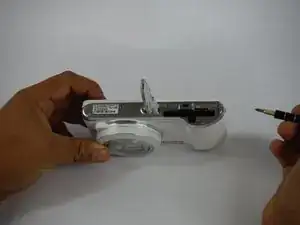
This guide was made for replacing the power button and zoom dial on the Samsung Galaxy Camera 2. If your camera is hesitant about taking pictures or the zoom dial is jammed or broken, this is the guide for you. Be sure to remove the battery before attempting any repairs!
-
-
While holding the camera, take note of each screw holding the screen to the main chassis of the camera.
-
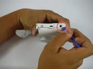
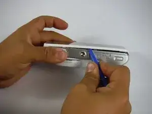
Hold the camera upright and lens facing towards you. There area total of six 4mm PH00 screws to undo - two on the left, one screw on the right, and three along the bottom. Two of them are hidden behind the battery compartment door.
-
-
-
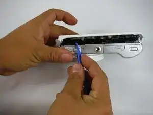
With the screws removed, use the plastic opening tool to gently pry the screen away from the main camera chassis. The ideal spot to start is at the corner with the headphone jack, as indicated in the picture.
-
Once this side is free, gently work your way along the edge, all the way around the camera body.
-
-
-
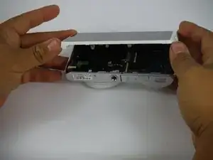
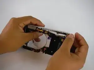
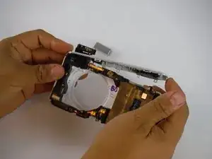
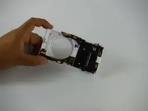
With the screen freed, gently lay the camera on its face, so that the battery compartment faces up. Use both hands to lift the screen up and away.
-
-
-
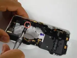
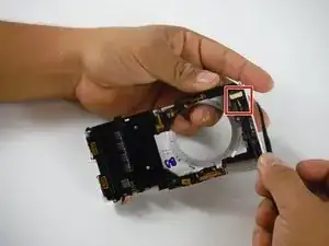
With the screen separated from the main chassis, use the plastic opening tool to gently pry the edge of the ribbon cable connector from the motherboard.
-
-
-
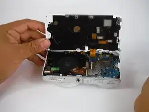
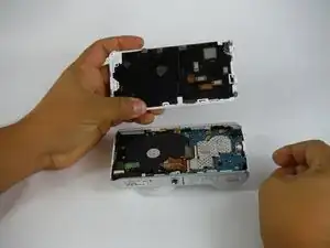
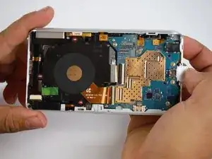
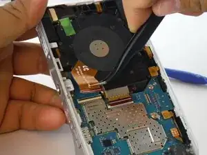
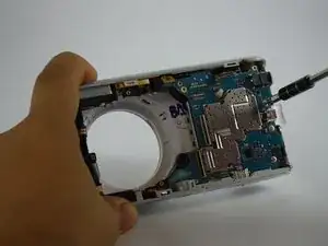
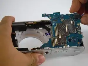
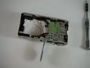
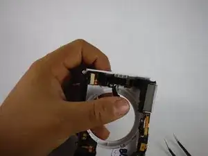
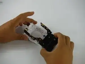
After removing the screen and battery to access to the inside of the camera, take note of the two main assemblies inside-- the lens apparatus and the main motherboard. The lens assembly is on the left hand side.
-
There are three small silver screws (4mm PH00) to remove.
-
-
-
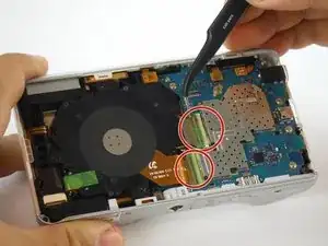
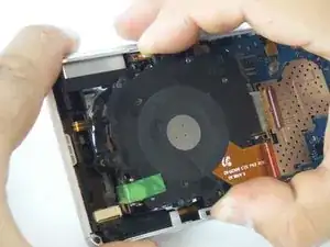
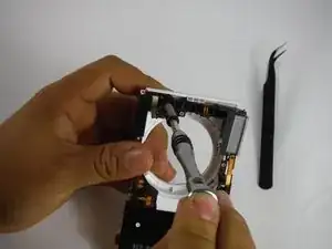
With the three screws removed, take note of the two ribbon cables connecting the lens assembly to the main motherboard.
-
Use the tweezers to remove the two green strips of tape protecting the connectors.
-
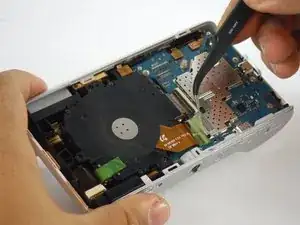
Use the plastic opening tool to release the black clips locking in the ribbon cables, then use the tweezers to gently pull the ribbon cables away from the main motherboard.
-
-
-
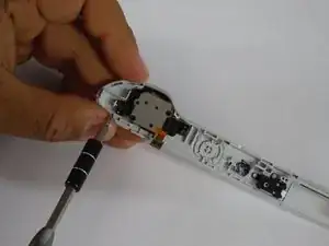
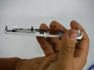
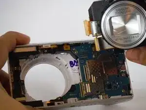
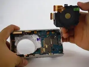
Now that the screws and ribbon cables have been removed, gently pull the lens assembly up from the the camera and remove it.
-
-
-
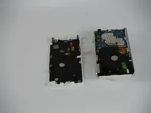
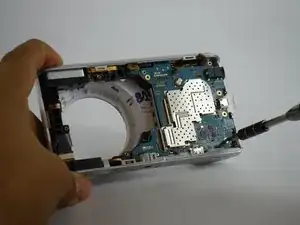
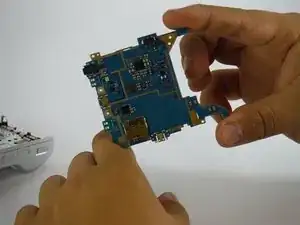
Now that you've removed the battery, screen, and lens assembly, you are ready to continue inremoving the motherboard.
-
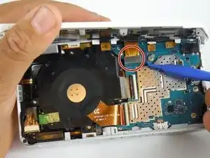
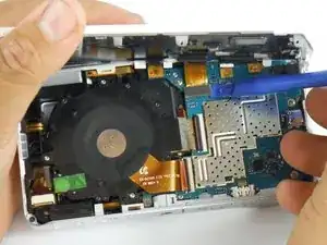
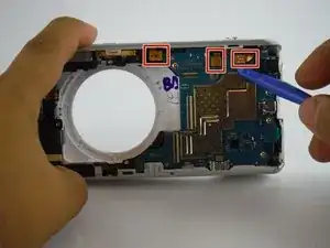
There are small ribbon cables connected to the motherboard. Use your plastic opening tool and gently pry the sides of the connectors away from the motherboard. Tuck them away to prevent damaging them when removing the motherboard.
-
-
-
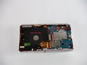
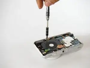
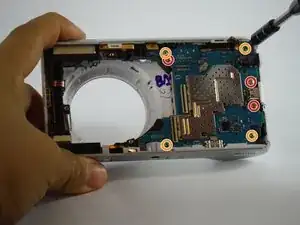
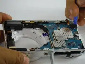
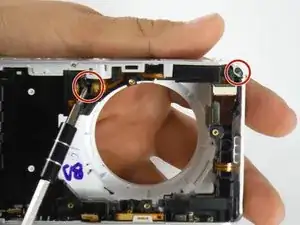
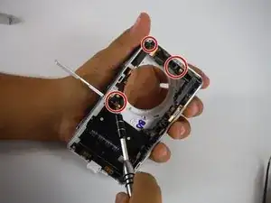
After removing the ribbon cables, take note of the screws holding the motherboard into the main chassis of the camera.
-
There are two types of screws to remove. The four (2mm, PH00) circled in red have a fat head, and go in the gold contact.
-
The three (4mm, PH00) screws marked in green have a skinny head.
-
Use the IFIXIT screwdriver and PH0 bit to remove all the screws holding the motherboard.
-
-
-
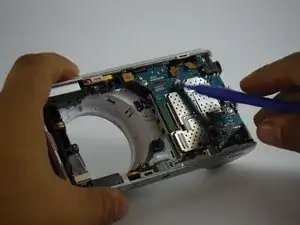
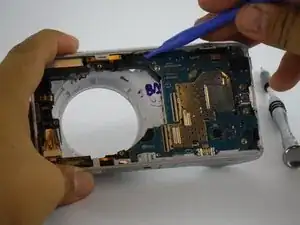
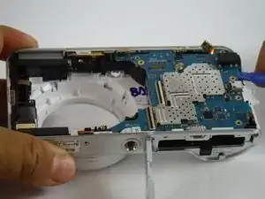
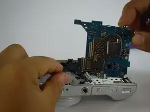
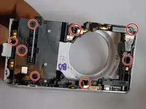
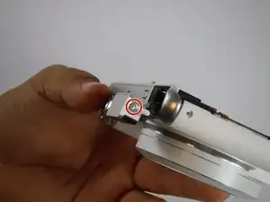
With all the screws removed, use the plastic opening tool to gently pry the headphone jack away from its casing. That jack holds the motherboard in place.
-
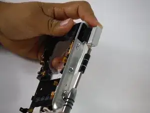
Next, gently slide the plastic opening tool underneath the motherboard. Move your fingers underneath and use your hands to completely remove it.
-
-
-
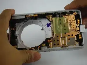
Having completed the previous guides up to this point you should be left with the chassis and internal frame exposed
-
-
-
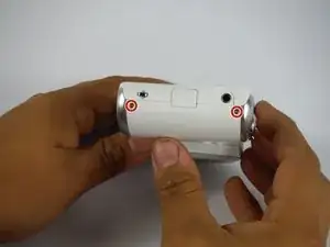
Start by removing nine (4mm, PH00) of the screws which hold the outer silver trim bezels to the main chassis highlighted in red.
-
-
-
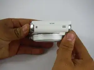
First remove the silver trim bezel on the battery-door side which should pop straight out. The silver trim on the flash side requires the removal of two hidden screw (2mm, PH00) on the underside of the top of the camera. one is above the lense hole, and the other is by the spring on the flash side of the camera. They are marked in red.
-
With the screw removed, gently pull up on the silver trim to release one side. It will still be attached to the camera until the next step.
-
-
-
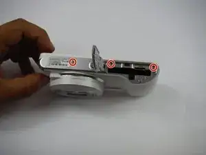
Open the flash and remove the silver plastic cap on the flash which has two screws (3mm, PH00). They are on either side and marked in red.
-
Then, use your hands to completely remove the silver trim containing the zoom and power buttons.
-
-
-
Using the iFIXIT curved nose tweezers, gently remove the ribbon cable for the flash. Doing so will reveal yet another hidden screw. Remove this with the iFIXIT screwdriver and PH00 bit to release the flash assembly.
-
-
-
Take the flash assembly and set it aside while you complete the tear down of the camera.
-
With the flash assembly removed, gently pull the rest of the internal frame away from the casing to expose every last piece of the camera.
-
-
-
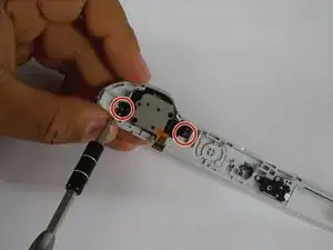
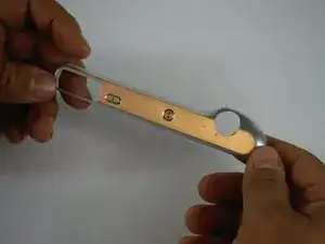
Now with the camera completely disassembled, take the silver trim with the zoom and find the two screws holding the zoom-button assembly.
-


To reassemble your device, follow these instructions in reverse order.
3 comments
Has anyone found a source to purchase a replacement button/zoom assembly?
The clip that holds the battery in the camera is broken so the camera is t taking a charge
The clip to close the camera where the battery goes is broken