Introduction
Changing the USB port for this model is tricky.
One option would be to replace the connector only, but a resin glue makes it difficult to unsolder the USB connector.
I therefore decided to replace the entire PCB.
However, but this proved to be also really tricky because the PCB is a rigid-flex board with a lot of very tiny flex parts, and I ended up braking the flex part around the jack connector while attempting to remove the PCB. I also damaged the screen while attempting to lift the glass.
So carry out this procedure with great caution!
Tools
-
-
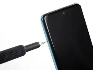
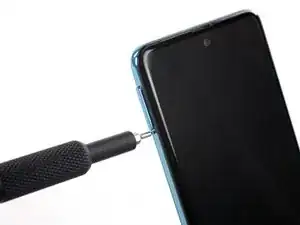
Insert a SIM card eject tool, a SIM eject bit or a straightened paper clip into the hole on the SIM tray located at the left side of the phone.
-
Press firmly to eject the tray.
-
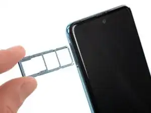
Remove the SIM card tray.
-
-
-
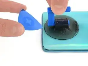
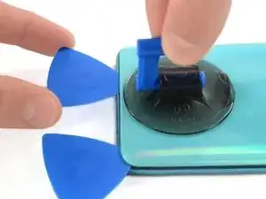
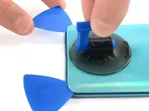
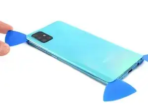
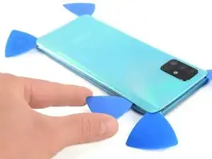
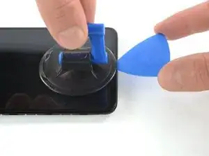
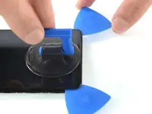
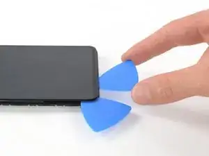
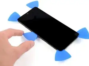
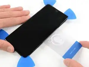
Insert the tip of an opening pick between the frame and the back cover at the bottom of the phone near the USB-C port.
-
If you can't get between the back cover and midframe with your opening pick, you can use a suction handle or strong tape to pull up the back cover to create a gap.
-
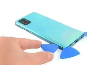
Slide the opening pick to the bottom right corner and leave it there.
-
-
-
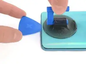
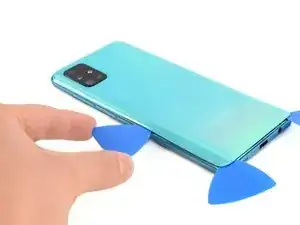
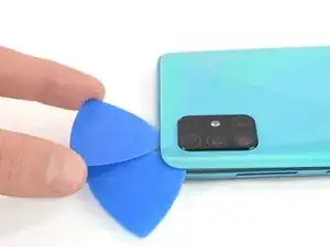
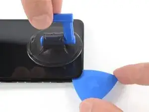
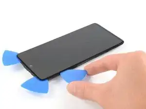
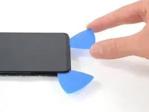
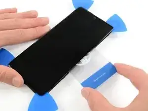
Insert a second opening pick and slide it from the bottom right corner to the bottom left corner to cut the adhesive.
-
Leave the opening picks in place to prevent the adhesive from resealing.
-
-
-
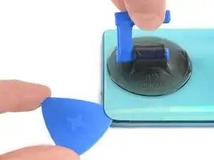
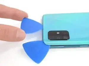
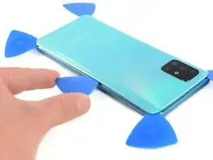
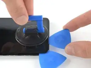
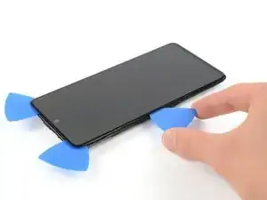
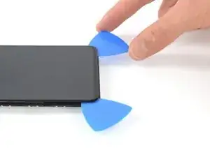
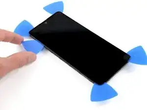
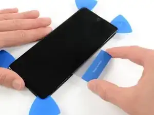
Insert a third opening pick under the bottom left corner of the back cover.
-
Slide the opening pick along the left edge of the phone.
-
Leave the opening pick in the top left corner to prevent the adhesive from resealing.
-
-
-
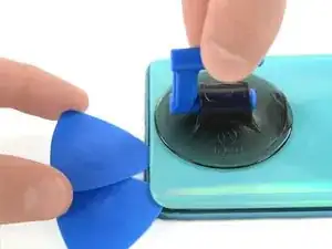
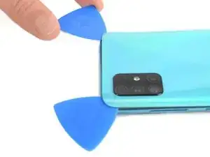
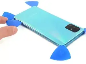
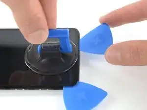
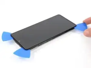
Insert a fourth opening pick under the top left corner of the back cover near the camera.
-
Slide the tip of the opening pick along the top edge of the phone to the right corner to cut the adhesive.
-
Leave the opening pick in the top right corner to prevent the adhesive from resealing.
-
-
-
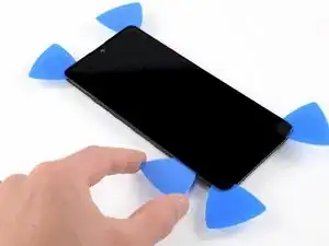
With opening picks in all four corners, insert a fifth and final opening pick under the top right corner of the back cover.
-
Slide the tip of the opening pick along the right edge of the phone to the bottom right corner to cut the remaining adhesive.
-
-
-
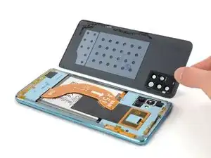
Use the flat end of a spudger to pry up and disconnect the display flex cable on the bottom of the phone.
-
-
-
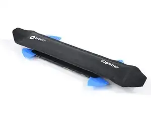
Prepare an iOpener and apply it to the display for at least two minutes to loosen the adhesive beneath.
-
-
-
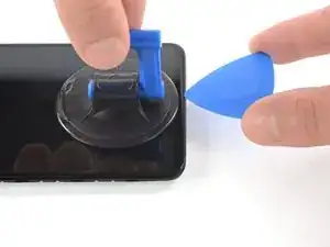
Once the screen is warm to the touch, apply a suction cup to the upper edge of the phone.
-
Insert an opening pick in the gap and start to cut the adhesive by sliding it to the top right corner.
-
-
-
Insert a second opening pick and slide it to the top left corner.
-
Leave the opening picks in place to prevent the adhesive from resealing.
-
-
-
Insert a third opening pick and slide it along the left edge to cut the adhesive.
-
Leave the opening pick in the bottom left corner to prevent the adhesive from resealing.
-
-
-
Insert a fourth opening pick and slide it from the bottom left corner to the bottom right corner.
-
Leave the opening pick in its place to prevent the adhesive from resealing.
-
-
-
Insert a fifth opening pick and slide it along the left edge of the phone to cut the remaining adhesive.
-
-
-
Reapply a heated iOpener to the screen to loosen the adhesive underneath.
-
As you wait, take note of the rectangular-shaped adhesive placed underneath the screen.
-
-
-
Insert a plastic card on the left edge into the gap between display and the phone assembly.
-
Press the plastic card in and slide it back and forth until you cut through the entire adhesive.
-
Once you are sure you cut through the adhesive, remove the four opening picks from the corners.
-
-
-
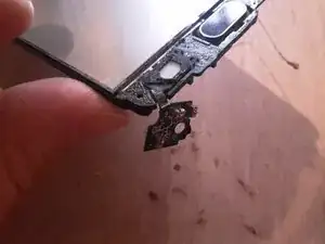
Use the flat side of the spudger to unglue the microphone from its compartment. Be careful not to break the flex part.
-
-
-
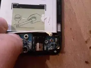
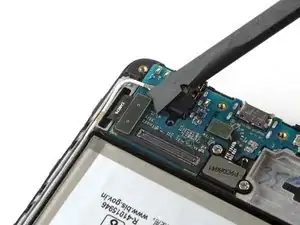
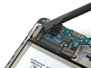
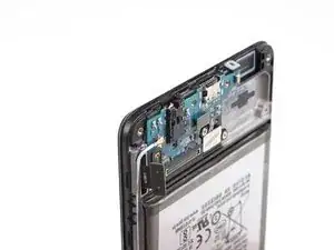
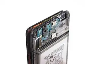
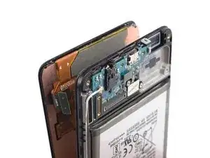
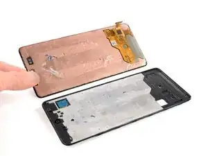
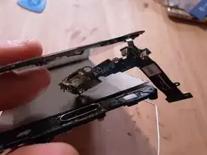
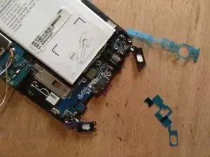
Peel off the PCB from its compartment and lift it to the other side without pulling.
-
Proceed element by element, trying not to break the flex parts. Here you’ll notice I broke the flex surrounding the jack port.
-
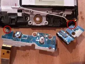
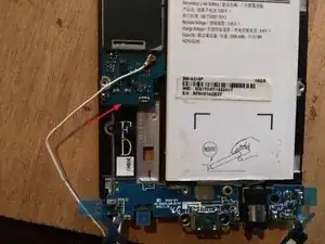
Take care not to damage/disconnect the two flex cables connected to the buttons at each end of the PCB (circled in red on the photo)
-
-
-
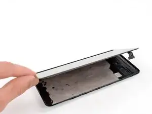
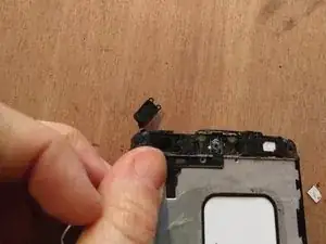
Remove or raise the glass on the other side of the phone.
-
Peel off the two button connectors.
-
-
-
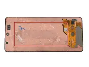
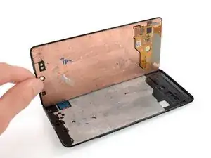
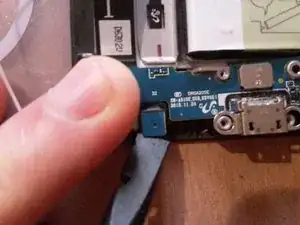
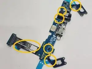
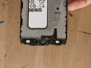
This is a view of the entire replacement board.
-
Note the flex parts circled in yellow on the photo: those are the most fragile parts of the PCB.
-
-
-
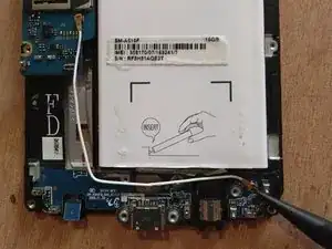
Place the new USB board in its casing
-
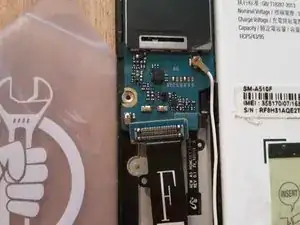
Plug the connector to the main board, below said board
-
-
-
Remove stickers from glued parts on new board
-
Remove the previous while filtering sticker under the buttons
-
Glue both backlight elements into their casing
-
-
-
At this point, there are 17 screws to be reassembled at the back of the phone
-
Glue screen and back cover back in place
-

Follow the instructions in reverse order to assemble the device.

Kijk uit voor de vingerafdruk scanner. Er zit een kleine flat cable aan die kapot gaat als je de behuizing er in 1 keer vanaf haalt
Arno van Duijn -
Falls der vorherigen Kommentar nicht verstanden wird, hier nun die Übersetzung 😉 Achte dabei auf den Fingerprint Scanner, da ist ein kleines flaches Kabel dran welches kaputt geht wenn Du die Hülle auf einmal entfernst.... also Vorsicht ist hier wohl geboten, wenn man sich an dieses scheinbar Einfache heran macht.
Sylvia L. -
Ik kan helaas niet de simkaart houder met sim. Eruit halen. In de S9 plus de sim kaart blijft achterwege.
Deden -
????????????
Deden -