Introduction

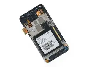
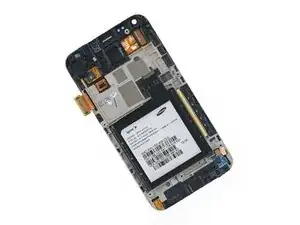
Use this guide to replace your front panel assembly.

  1. wqDMulqHJIFVaJNg
    wqDMulqHJIFVaJNg
    6JTCgiHZhtXUDvKD
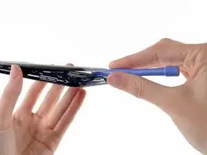
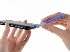
    • Insert a plastic opening tool, or your fingernail, into the opening near the left side of the headphone jack.

    • Pry the opening tool downward to pop the rear case from its clips securing it to the the midframe.

  2. XTdPY2DfE2Jwyln5
    XTdPY2DfE2Jwyln5
    l4FvI1NeHoGT2nWH
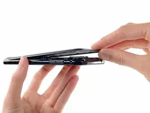
    • Lift and remove the rear case.

  3. JqhPxZDw2GhgMFYT
    JqhPxZDw2GhgMFYT
    lbsG63GhxCaKJZwK
    • Use the flat end of a spudger, or your fingernail, to press the microSD card slightly deeper into its slot until you hear a click.

    • After the click, release the card and it will pop out of its slot.

    • During reassembly, push the microSD card into the slot until it clicks in place.

  4. QGnkRohCGFGKYENl
    • Pull the microSD card away from its slot.

  5. xQuVIjO1hjcbvSL1
    xQuVIjO1hjcbvSL1
    dme2rWXTVia61PsU
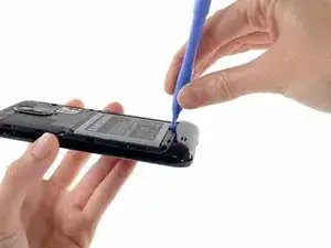
    • Wedge a plastic opening tool into the crevice between the battery and midframe located near the bottom left corner.

    • Push the plastic opening tool downward to pry the battery up from its housing.

  6. IYrPokZTaL6OHyhs
    IYrPokZTaL6OHyhs
    hZRed2fsCHSnZMPS
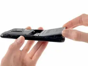
    • Lift and remove the battery from the midframe.

  7. ApfsXVLvcCyaYyCZ
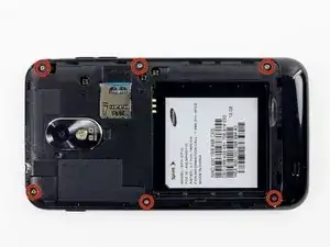
    • Remove the six 4.0 mm Phillips #00 screws securing the midframe to the front panel assembly.

  8. SJQshJuXClXNlKPE
    SJQshJuXClXNlKPE
    alCWdAsEbuMuTxYI
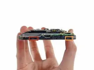
    • Unless you pry at the right insertion points, you might have a difficult time removing the midframe. This shot of the display assembly, with display glass facing down, is meant to help you locate them.

    • The first insertion point is a divot to the left of the micro-USB port.

    • The second insertion point is a divot to the right of the micro-USB port near the corner of the phone.

    • The final insertion point is located about two inches to the right of the volume control toggle, toward the corner of the phone. An additional insertion point is located slightly to the right of the volume button if you need it.

  9. pnVqsI1vjZvTr2aM
    pnVqsI1vjZvTr2aM
    qUL1JI4dXU6oexgg
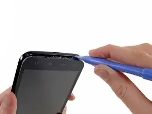
    • Insert a plastic opening tool slightly to the left of the micro-USB port, and pry between the midframe and the display to open a gap.

  10. EwuEacEvIrZPcKCr
    EwuEacEvIrZPcKCr
    iRsKItTuBd3tGVQS
    • Wedge a plastic opening tool slightly to the right of the micro-USB port, and pry between the midframe and the display to widen the gap.

  11. ijZXKLAXDdUSPbDq
    ijZXKLAXDdUSPbDq
    OGmFdG5UPZwDHYJj
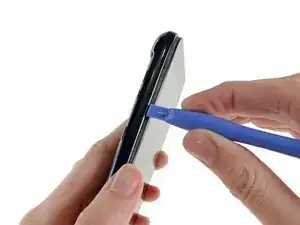
    • Pry again about two inches to the right of the volume control toggles between the midframe and the front panel assembly.

  12. JCdA1SFHFWIMqiBi
    JCdA1SFHFWIMqiBi
    XEu3PCjATFoqaHIf
    • Pull the micro-USB end of the front panel assembly out and away from the midframe and lift up to free it entirely.

  13. jGWPNIF6YFfrTNsm
    • Headphone jack/vibrator assembly cable connector

    • Front-facing camera cable connector

    • Digitizer cable connector

    • Display cable connector

  14. s4LQFdXe4QHxbQFs
    s4LQFdXe4QHxbQFs
    sY5ysEBIX6IRBqBJ
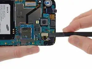
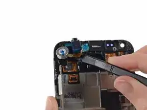
    • Use the flat end of a spudger to disconnect the headphone jack/vibrator assembly cable.

  15. tqpWq6IPq1jpNCDY
    tqpWq6IPq1jpNCDY
    Omklc6AifpNw6HwJ
    • Use the flat end of a spudger to disconnect the front-facing camera cable connector.

  16. dOUFBZR4iDj2lqhc
    • Carefully disconnect the digitizer display cable.

  17. viTWtCu66o4yMvQP
    • Use a spudger to disconnect the display cable connector.

  18. fm2NZpFvfF5uSUpW
    • Remove the two 3 mm Phillips #00 screws.

  19. KCWDY1GlhYsDInuo
    KCWDY1GlhYsDInuo
    LE5ooosvdAB1Wu2X
    3VsG5VREFHQQwKfN
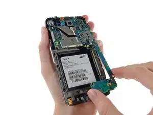
    • Lift the micro-USB end of the motherboard away from the display assembly and pull it down.

    • Be mindful that you don't snag the motherboard on any cables as you remove it.

  20. iIAvXB2lSILu2q2h
    iIAvXB2lSILu2q2h
    pFM46TQ4Ekk3JvDW
    • The microphone cover fits in a notch and over a small peg in the display assembly, ensure it is well seated before sealing your device.

    • Make sure the microphone cover stays in its slot on the display assembly.

    • When you removed the motherboard, the microphone cover may have remained stuck on the microphone. Put it back in its notch in the display assembly to avoid losing it.

  21. KLtJPHUCQcsfIRIs
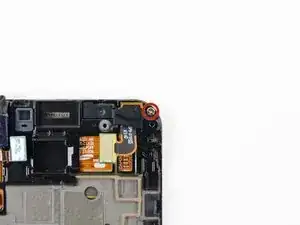
    • Remove the 2.3 mm Phillips #00 screw securing the front-facing camera bracket to the display assembly.

  22. 3KKJB4eULhaXJyhi
    • Remove the front-facing camera bracket from the display assembly.

  23. Dy3dKZw1doNtaWMr
    Dy3dKZw1doNtaWMr
    SskaMSmFhVCGT5NI
    • Using a pair of tweezers, or your fingers, remove the front-facing camera/earpiece speaker assembly.

  24. bulLULJRE1FuWZQI
    bulLULJRE1FuWZQI
    bBluOgDhCGmTpYMC
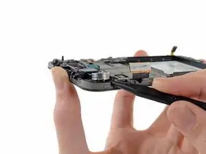
    • Insert the pointed end of a spudger into the gap in the corner of the midframe to free the vibrator from the adhesive.

    • Do not completely remove the vibrator, it is still attached to the headphone jack/vibrator assembly and can only come out with the rest of the unit.

  25. OUih2HgNE1NoyY4N
    • Use the flat end of a spudger to release the headphone jack from the adhesive securing it to the midframe.

  26. 3goe1KKDMbMIlNtJ
    • Remove the headphone jack/vibrator assembly from the display assembly.

  27. JKxAbxQiDLH4ISv4
    • Front panel assembly remains.

Conclusion

To reassemble your device, follow these instructions in reverse order.

Sam Goldheart

Member since: 19/10/12

465329 Reputation

2 comments

My display is broken but the touch screen still works. How do you replace the display?

atworktom -

I attempted to replace the display glass alone on a Virgin Mobile Galaxy SII, and was unsuccessful. Removing the Glass from the Digitizer proved to be extremely difficult. It seems as if the Virgin Mobile version of the SII is not meant for repair, so easily.
Edward Weissbard -