Introduction

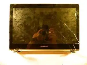
The graphics screen is nested behind the capacitive touchscreen. Therefore, in order to replace the graphics-screen it is mandatory to remove the capacitive touch screen first. This guide will show the user the proper way remove the graphics-screen.

  1. TUXv3eByCDElqQ2j
    TUXv3eByCDElqQ2j
    JN5ImH6lv4MLi3Xm
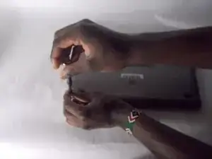
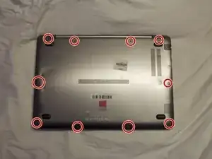
    • Remove the ten 5 mm screws that hold the backplate using the Phillips #000 screwdriver.

  2. pFDxBv3YFAs2MOgZ
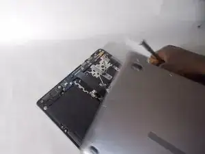
    • Remove the backplate.

  3. 6C64K6W2URGTNhvm
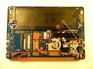
    • Disconnect the databus from the motherboard as seen in the lower left of the picture

    • Disconnect the white and black wire from the graphics card as seen in the middle of the photo. (Note: These two wires are connected to the motherboard by means of snap-in male-female copper connectors, meaning they can be disconnected by un-snapping the connectors.

  4. sjSmyn2aaiAxJmWR
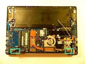
    • Using the Phillips #000 screwdriver, remove six 5mm screws.

    • These screws hold the screen assembly into place with the motherboard / electronics assembly.

  5. obxKxNDKREse5ZKF
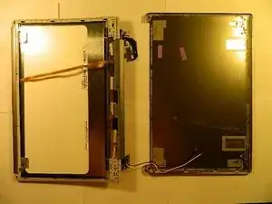
    • Now that the six 5mm screws were removed, remove and separate the screen assembly as seen in the image.

    • As seen in the next step, the backplate of the screen assembly will be removed. There is no hardware keeping this in place except for adhesive glue. Therefore the screen assembly backplate will be gently pried free.

  6. UUVpJNQf13AB2IHm
    • The screen assembly backplate is to be removed

    • The backplate is adhered around the edges. Using a flat-wedged tool, gently pry the backplate free from the assembly.

  7. HtGFOnfHu1QtuXSu
    HtGFOnfHu1QtuXSu
    JND2ZsxRloKgDwSs
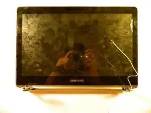
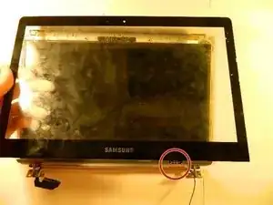
    • Now that backplate has been removed, flip the laptop over on the front. Remove the capacitive touch screen.

    • Similarly to how the backplate was adhered with glue, this touch screen is adhered to the graphics screen of this device. As seen in the second photo, the touch screen should be gently separated from the graphics screen. Make sure to disconnect the ribbon as circle in the photo.

  8. GPXZqZLESiyIZPht
    GPXZqZLESiyIZPht
    VD4KL5FJehxEDWuL
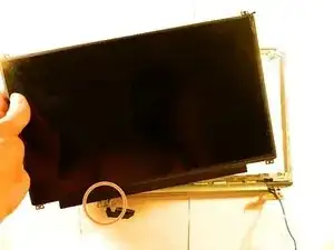
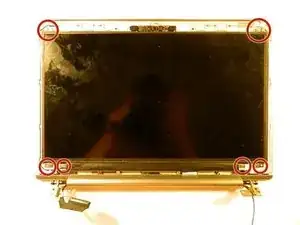
    • Remove the six 3 mm screws using the Phillips #000 screwdriver.

    • This will free the graphics-screen from the holding assembly as seen in the second photo.

    • Unhook the ribbon connection.

    • Remove the screen.

Conclusion

To reassemble your device, follow these instructions in reverse order.

Important Note: When re-assembling the screen assembly, additional adhesive glue may be needed to adhere the graphic-screen, capacitive touch-screen and screen cover back onto the original assembly.
Liam

Member since: 26/03/19

223 Reputation

0 comments