Introduction
This guide is a step-by-step process showing how to get to and remove the wiring harness within the handle of this grinder. This may be helpful in determining an issue with powering the device or replacing faulty wiring. As you work though this guide you will notice number following capitalized parts. These are the key numbers from the visual diagram provided within the Technical Description/Device Page under Additional Information, labeled 'Parts Page and Wiring Diagram.' Steps 1 through 3 are not necessary for this task although they make it easier to work with the tool.
-
-
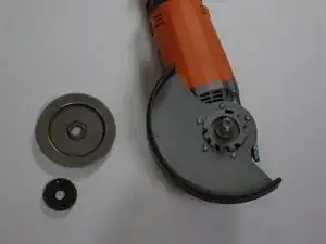
To get to the guard, unscrew and remove the Clamp Nut [34], Grinding Wheel (not pictured) [35], and Backing Flange [36].
-
-
-
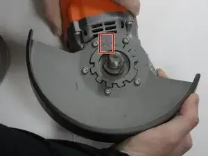
To remove the Guard [38], press and hold the Guard Lever [39] and rotate the head to line up the two arrows inlayed within the metal as seen in the photograph provided.
-
Once the arrows line up lift the Guard [38] from the grinder.
-
-
-
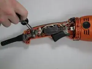
Use TORX T20 Screwdriver to unscrew and remove 5 M5 x 16 mm, TORX Screws [28].
-
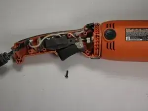
Use TORX T20 Screwdriver to unscrew and remove 1 M5 x 28 mm, TORX Screw [1].
-
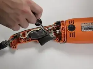
Use TORX T10 Screwdriver to unscrew and remove 1 M3 x 10 mm Screw [26].
-
-
-
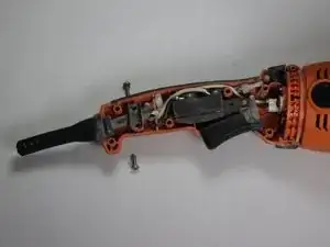
You should now be able to separate each side of the Handle Assembly [27] as seen in the first photograph.
-
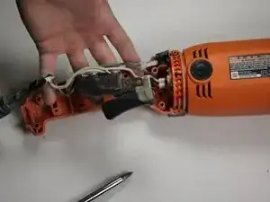
Remove the side that should easily separate from the other.
-
-
-
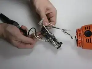
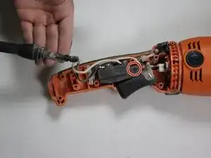
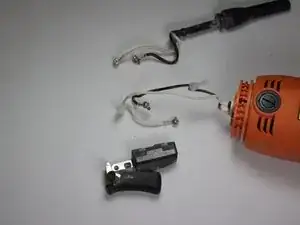
The whole wiring assembly should be able to be lifted out of where it currently is as seen in the first photograph.
-
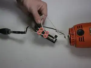
Press and hold the Handle Lock Button [24] to release the second side of the Handle Assembly [27].
-


To reassemble your device, follow these instructions in reverse order.
One comment
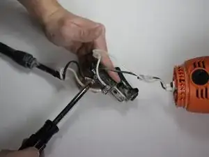
Be careful while jointing the wires because it can cause you some electric issues for more info you can read this guide.
Fahed -