Introduction
This guide will show you the steps to correctly disassemble the camera and replace the flash that is not working. 26 Piece Bit Driver Kit which can be purchased from www.ifixit.com will be most useful for repair, but other small screwdriver kits can be used.
Tools
-
-
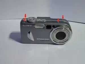
Unscrew 4 screws on top of camera.
-
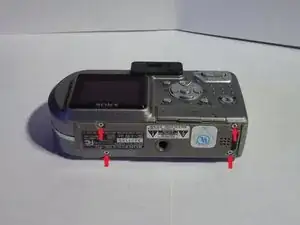
Unscrew 4 screws on bottom of camera. (Picture 2)
-
When all 8 screws are out, remove front and back cover from camera.
-
-
-
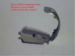
Remove this piece located on the right side of the camera.
-
This piece can by removed by lightly pulling off of the camera.
-
-
-
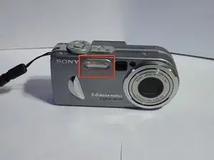
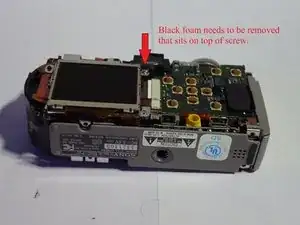
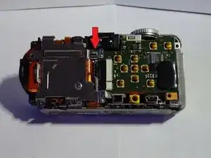
Begin by removing the small piece of black foam located at the top right of the LCD screen. (Picture 1)
-
Remove screw which is located exactly where the black foam was. (Picture 1)
-
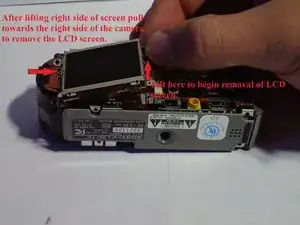
After screw is removed lift right side of LCD screen straight upward and pull to towards the right side of the camera. (Picture 2)
-
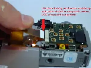
The LCD screen will pull out of the camera and 2 ribbon circuits will need to be detached.
-
Detach both by carefully pulling out of black locking mechanism. (Picture 3)
-
-
-
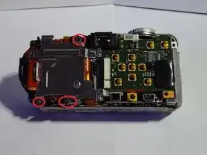
Remove the three screws holding the metal backing down. (Picture 1)
-
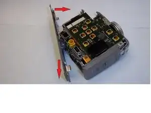
Push on the plastic piece near the top right of the metal backing and lift the backing up to release the top half. (Picture 2)
-
Pull the metal backing towards the bottom of the camera to free it from the lower right catch. (Picture 3)
-
Lift the metal backing up and off of the camera.
-
-
-
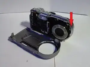
Disconnect the two ribbon circuits on the front of the camera.
-
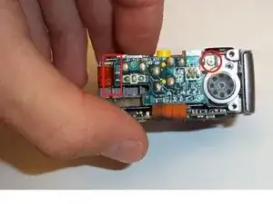
The camera should now be in two parts. Set the lens half off to the side and continue working with the side containing the flash.
-
-
-
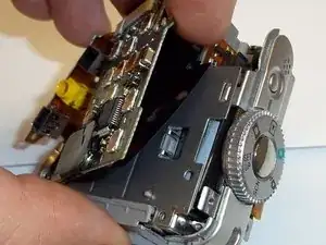
Lift the left side of the bottom panel towards the top of the camera.
-
Then pull the panel down and away from the camera.
-
-
-
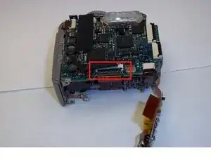
Remove the screw at the upper right corner. (Picture 1)
-
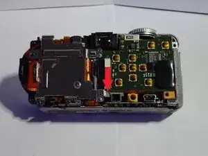
Carefully work the ribbon circuit, pictured at the left side, back and forth to free it from the plastic retainer. (Picture 1)
-
Lift the black locking mechanism up (Picture 2) and gently pull the ribbon circuit to detach.
-
Upon completion of this step, the lower circuit board should be attached in one place and be freely hanging as shown. (Picture 2)
-
-
-
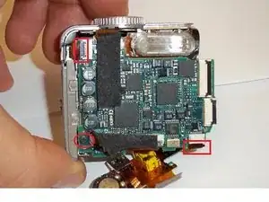
Remove upper left ribbon circuit by lifting black locking flap and gently pulling out.
-
Remove the lower right ribbon circuit by gently pulling out.
-
Remove the lower left screw.
-
-
-
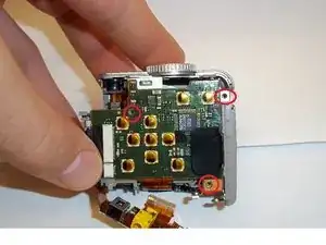
Remove the three screws securing the rear circuit board.
-
Lift up on the left side of the circuit board and gently pull to the left to dislodge.
-
-
-
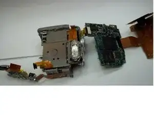
Gently lift the rear circuit board away from the camera.
-
Rotate the circuit board 180 degrees so that it is directly below the camera.
-
Now gently remove the front circuit board and rotate both the rear and front circuit boards 180 degrees so that they are directly above the camera (picture 2).
-
-
-
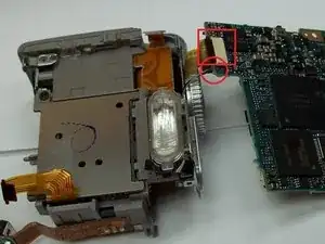
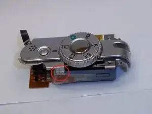
Lift the black locking mechanism up and gently pull the ribbon circuit free.
-
Remove the wires by using a tweezers to grasp the white plastic plug and pull gently until free.
-
Note: The wires shown by the red circle are connected on the opposite side as the ribbon circuit.
-
-
-
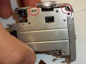
Using the tip of the tweezers, press on the latching mechanisms one at a time to free the flash housing piece.
-
Once the flash housing piece is free gently pull up to remove.
-
Note: You may have to wiggle the flash housing back and forth to free the circuit board located on the bottom of the flash housing
-
-
-
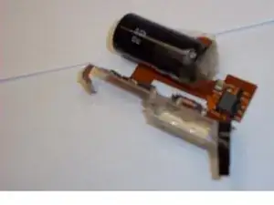
Remove the tape to release the top half.
-
The Half with the circuit board is the built-in flash.
-
You have successfully removed the built in flash!!
-
To reassemble your device, follow these instructions in reverse order.