Introduction
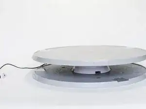
This concerns a process description to repair a carrousel by replacement of an internal gearwheel.
Although the specific equipment is a carrousel, the description can be regarded as typical for the task “how to 3D print a gearwheel as a replacement in an existing gearbox”.
This process is also known as 3D Printing For Repair, abbreviated as 3DP4R.
This production is a collaboration of
TU Delft Industrial Design Engineering (printing of parts)
Henk Pouw (photography)
The open-source 3D modelling program OpenSCAD and as an addendum, its general purpose gear library
For more information and in-depth theory see:
a thorough introduction in 3DP4R from TU Delft
-
-
The turntable housing has two parts: a base and a cover. The table shaft runs through the cover and has a bottom centering point in the base housing. The gear wheel is mounted on the shaft with screws (not shown). The gearwheel has a groove, 1 mm deep, that fits into an annular ring of the cover, providing a top centering point.
-
All injection moulded parts are anonymous, i.e. they show no identification marks, by number or trade name. Motor rating is 3V 0.5A DC, max turntable load is 20 kg.
-
-
-
The gearwheel turns out to be broken, probably due to an unbalanced load of the table during transport Gearwheel is broken at its smallest cross section point: where the width is reduced to give room to the shaft notches.
-
The gearwheel has a triple function: gearwheel, centrepoint and ring to prevent that the turntable can be pulled out of the upper part of the housing. The gearwheel is driven by a brass worm-wheel, the motor shaft also has a brass worm-wheel. We do not bother here why there are only three legs.
-
photo shows part upside down as assembled
-
-
-
Apart from number of teeth and pitch, a modelling program also needs the angle of the teeth. This is a method to obtain it.
-
The major concern is to ensure that the camera view is perpendicular to a tangent line touching the gearwheel.
-
Close to the edge a hole is drilled in a piece of plywood, the top is then covered with a piece of white paper, for a good distinction the front side is covered with paper in a contrasting colour.
-
The plywood piece, including paper and hole, must be really flat.
-
A pin is pushed upwards through the hole, the wheel is pushed against this pin and the wheel is used as a template to draw the circumference on the paper. Remove the gearwheel.
-
Set a pair of compasses to the radius of the wheel. Put one of the compasses on a point on the circumference, draw a circle segment close to the centre. Repeat the process using another point on the circumference. The two lines drawn result in a cross hair and reveal the centre of the gearwheel.
-
A second pin is pushed in the centre.
-
Align these two pins in the camera viewer, to ensure that it is perpendicular to the tangent line through the circumference pin.
-
-
-
The gearwheel is aligned with the circumference, and pushed against the circumference pin so that the pin is firm in the corner of the teeth bottom. The centre pin is removed. Then a picture is taken. During the process be sure not to disturb the camera and plywood position.
-
-
-
Print the image, with a width/height ratio identical to the original image.
-
Determine pin angle by measurement Alt. import the image in LibreOffice draw or other appropriate software. In an empty draw document insert a horizontal line with minimal thickness. Import the image.
-
Align the edge of the plywood to the line, by rotation of the image (select + F4) Draw a second ‘vertical’ hairline and by rotating/moving, align it with the pin. The angle is determined as 4.6 degrees in this instance.
-
Keep the aspect ratio equal to the original image, if enlarging/reducing the image size.
-
-
-
OpenScad has been used to model the gearwheel, using the public available gear library, based on DIN 780. Another standard is the ISO 6336. No attempt has been made to determine which standard will have been used for the original wheel. The choice has been made on the basis of availability.
-
3DP4R parts are notably less strong than injection moulded parts, therefore the original part is modified by adding more volume and a 45 degrees fillet in internal corners.
-
A module (or pitch) of 0.6 mm is a discrete choice using DIN 780, with a count of 73 teeth and an addendum of 2*0.6 for the teeth height, this gives a diameter of 0.6*73+1.2 = 45.0 mm. The measured diameter of the original part is 45.3 mm.
-
-
-
3DP4R is an iterative process to obtain the desired part, while adjusting the 3D model, printer technique/settings and material. The table gives a summary of the successive parts printed, each with an infill of 100% for reasons of strength
-
FDM: fused depositing modelling (the standard amateur printer) SLA: a photopolymer resin in a vat is selectively cured by a light source SLS: solid layer sintering
-
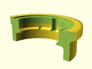
SCAD cross section shows the gearwheel with annular groove for centering, in the position as mounted on the turntable shaft. The wheel is fixed on the tableshaft by four nails inserted in the “pre-drilled” holes. An impression mark of the nail on the tableshaft has been used to drill four holes in the tableshaft.
-
-
-
The turntable housing is a closed box. During iteration steps 1-3 the results were judged by the sound of the motor / variations in rotational speed of the turntable.
-
All the parts 1-3 needed post processing before they fitted. This involved increasing the width (thickness) of the notch groove and sanding of the inner diameter.
-
-
-
1) the motor has difficulty to rotate the turntable, sometimes the table almost stopped With FDM printing the top groove requires support structures and accurate post processing to remove the structures. In the modelling this groove has been omitted, also because the importance of the groove was overlooked at the time.
-
-
-
2) results improved, but still variations is sound/table speed were present. For some reason we missed the opportunity to include the extra centering by a top groove in the gearwheel.
-
We turned to the SLA printing technique. To enlarge the clearance between worm-wheel and gearwheel we also scaled the gearwheel to 98.7 %, this reduces the radius by 1.3% * 45 / 2 = 0.3 mm. This has to be compared to the teeth height of 0.6 mm.
-
-
-
3) The first time the part has been printed with a top groove, the prints showed bubbles in the surface and deformations. Part 3B is the worst and was not used. When cover and wheel are assembled separately there is no radial clearance between cover and top centre groove.
-
The rotational performance decreased due to irregularities in the print, as a last resort the tooth bottom was enlarged with a few strokes with a fine iron saw blade. This led to an acceptable result, with a turntable load of 7 kg.
-
In a final attempt the parts were printed by a third party with the SLS technique and (glass filled) nylon as material. At the same time an inspection hole was made at the bottom, to be able to see what is going on at the intersection of worm- and gearwheel.
-
-
-
4) This is the first gearwheel that slipped in place without post processing. No notch adaptation.
-
- The radial clearance between cover and wheel is 0.5 mm, when cover is separate from the base housing.
-
- With the worm-wheel not present and the bottom of the housing installed the radial variation reduces to 0.2 mm: the bottom housing provides an extra centering point for the table shaft.
-
- With an installed worm-wheel the tolerance remains 0.2 mm (parallel and perpendicular to the worm-wheel), indicating that the wormwheel, in the extremes of the variation present, is free to move in the space between the gearwheel teeths.
-
At a minimal distance between worm- and gearwheel a gap of 0.1 mm is present at the teeth bottom, between the teeth a guestimated 0.2-0.3 mm remains. (physical measurement not possible)
-
This is confirmed by visual inspection. At a minimal distance between worm- and gearwheel a gap of 0.1 mm is present at the teeth bottom, between the teeth a guestimated 0.2-0.3 mm remains. (physical measurement not possible)
-
With a centred stone of 7 kg as load, there are still small variations present in sound of the motor. Upon removal of grease present in a plastic groove in the cover of the housing, holding the bearing balls, it turned out that the groove has an irregular wear pattern. This probably accounts for the variations in motor sound.
-
In hindsight the variations in sound for the parts 2 and 3 have been wrongly interpreted as “gearwheel is too large”. The variations are probably also caused by the irregular wear pattern in the turntable bearing.
-
The estimated times assumes knowledge of a 3D modeling program and a final result within 2-3 iterations.
In general the succes for gear wheel replacement is depending on
- the accuracy to center the gearwheel
- the ratio of teeth pitch over printer tolerance. In our case this ratio is about 1. Higher values of this ratio make the replacement easier.
This turntable is a low cost product (60 euro), using injection moulded parts. Although only four parts are involved, base housing - cover – shaft – gearwheel, the interaction of the four parts is subtle and has not been fully understood from the beginning. Inexperience and the initial inability to see how the assembled parts interact played a role here.
Injection moulded parts have a typical accuracy of 0.02 mm. This has to be compared to a tolerance of 0.5 mm for FDM printers and 0.3 for SLS printers and 0.2 mm for SLA printers. See link for an explanation of tolerance - accuracy - precision . It is hard to measure with a caliper existing diameters, distances and heights to model a fitting spare part, including the right minimal tolerance.
Apart from the measurements there are the variations in the actual size of the printed part. A printed part, with fixed modelling parameters, can be too small or too large depending on the technique (FSM/SLA/SLS) used, or using the same technique on another printer. Combined with the search for the right dimensions and tolerances this can lead to a large number of iterations / high repair costs.
In this particular case the process is hardly viable in a repaircafe setting.
The obtained results with respect to strength are for a runtime of several minutes only.
Upon redesigning the original part it turned out that the spare part has a strength that is sufficient to replace an injection moulded part. That is: at a load of 7 kg, the design maximum load is 20 kg.


