Introduction
The integrity of an accessory cable is very important. The shielding of a full speed USB cable is necessary to minimise EMI. The shielding must be connected to ground to be effective. When cables become frayed to the point that the shielding disconnects the cable is compromised and a source of interference to electrical devices. The higher the speed of the data transfer, the more important the integrity of the cable becomes. Therefore, it is necessary to keep USB cables in good order.
Parts
-
-
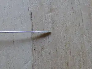
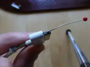
Take a pin with a plastic head. Place the tip over a flat, heavy duty surface (such as a cold chisel blade) and tap with a hammer to flatten. This should only take 5 to 10 taps. Make sure the blade is flat and the edge is smooth.
-
-
-
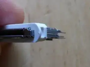
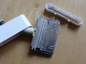
The 30-pin connector comprises of 3 parts: 1) the plastic outer shell, 2) the mid plastic sleeve, 3) the inner metal connector.
-
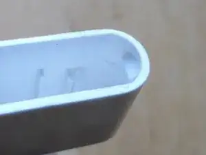
The middle sleeve has a lip on both rounded ends.
-
The outer connector has a corresponding plastic bump that snaps under the sleeve lip to hold them together.
-
-
-
Make a depth guide mark on the tool made in step 1.
-
The mark should start 3 mm from the tip of the tool.
-
-
-
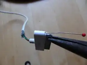
Work the tool between the outer shell and middle sleeve at one end of the connector until the depth mark is reached.
-
The plastic head on the tool will be very helpful to allow enough pressure to be exerted.
-
-
-
Once the tool is at the required depth and location that side of the sleeve and connector can be released.
-
Remove the tool and repeat on the other side of the shell. Be careful not to push the first side back in to the shell in the process.
-
Once both sides are released slide the outer shell down the cable.
-
-
-
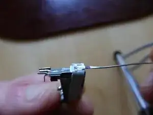
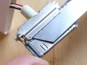
An Apple cable has a much more robust 30-pin connector than cheaper non-Apple cables. The Apple connector has 2 plates soldered to the back of it - one on the top and another on the bottom. Cheaper connectors do not have these shielding plates.
-
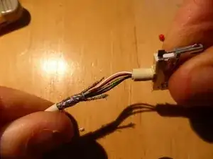
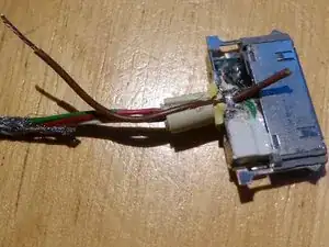
An Apple cable comprises of: 1) 4 wires, 2) a strain relieving thread, 3) shielding mesh around the wires and strain relieving thread, 4) outer cover.
-
-
-
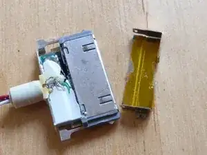
Access to the circuit board with the wire terminals is by removing the plate with 2 smaller solder points almost at the corners of the shielding plate.
-
Keeping the 2 solder points hot, work a flat bladed knife carefully between the shielding plate and connector so as to not cut the wires underneath until the plate releases.
-
-
-
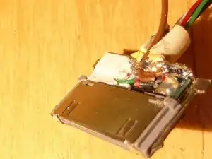
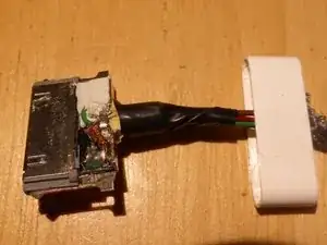
Here, only the shielding needs repair.
-
Carefully slit the external strain releaser.
-
Prise up the internal strain releaser.
-
Insert a piece of cable such as a strand of Category 5 cabling.
-
-
-
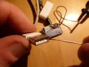
Test for continuity of shielding between 30-pin connector and USB connector. The resistance should be much less than 1 Ohm.
-
Test for short circuits between the 4 pins on the USB connector. There should be none.
-
-
-
Lightly wrap the wires with electrical tape.
-
Reinstall the cover plate.
-
Install the middle sleeve.
-
Slide the outer shell over the connector.
-
Wrap electrical tape from the back of the shell down the wires until it extends about 5 cm, reducing the overlap as you go. This will act as a poor man's external strain reliever.
-
To reassemble your device, follow these instructions in reverse order.
5 comments
This is a great guide. I figured out for myself, how to open iPod connector, but I could have saved some struggle if I had followed this guide.
What poop. They don't show the connections to solder to.
Tengo 3 cables desconectados sólo el verde soldado en un pin de un extremo rojo, blanco y negro dónde van?
Quiero volver a cargar la batería.
Carlos,
I did a search for ‘apple 30pin connector pinout’ and found this. I hope it helps.
http://mobilescomplaint.blogspot.com/201...
Tim
:)
tim -