-
-
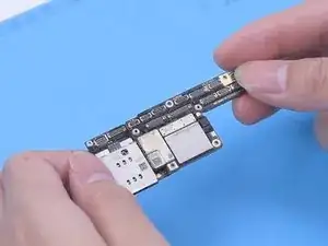
The iPhone X battery is draining fast with an overheating issue.
-
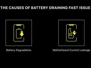
Battery draining fast is normally caused by battery degradation or motherboard current leakage.
-
After battery replacement, the battery is still draining fast. It can be judged that the problem is induced by motherboard current leakage.
-
-
-
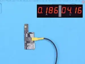
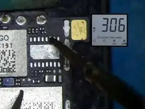
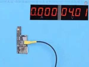
Next, we check the current by powering up the motherboard with a DC Power Supply. The motherboard has a current leakage of 186 mA.
-
-
-
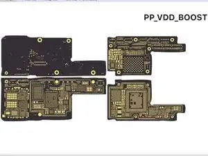
If the motherboard shows a current leakage after being powered up, we can measure the following power supply circuits to find the faulty part.
-
-
-
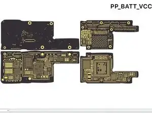
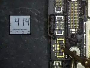
In the first place, we measure PP_BATT_VCC. The resistance value is normal.
-
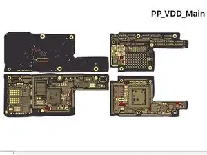
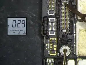
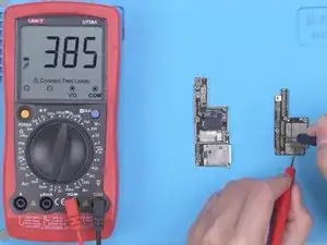
Then we measure PP_VDD_Main. The resistance value is 29 which is relatively low. It indicates that there is a damaged component on PP_VDD_Main. Since the current is small, rosin detecting is unable to find the faulty part. Therefore, we need to use a thermal imager to find the faulty part.
-
-
-
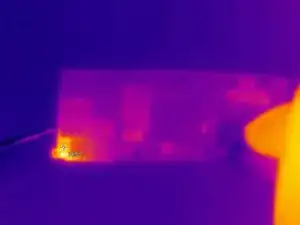
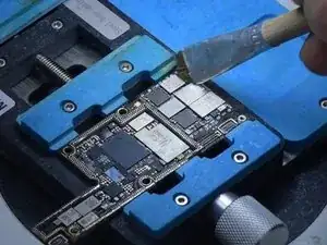
Power up the PP_VDD_Main on the motherboard. There is no obvious change in the temperature. The faulty part is not on the surface layer of the motherboard.
-
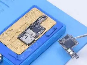
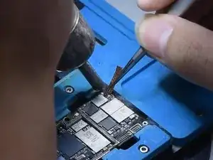
Then we separate the motherboard for further testing. Put the motherboard on the Heating Platform to heat. When the temperature reaches 165 °C, separate the logic board from the signal board.
-
-
-
After the motherboard has cooled, we firstly measure PP_VDD_Main of the logic board. The resistance value is normal.
-
Then we measure PP_VDD_Main of the signal board. The resistance value is abnormal. So we can confirm that the faulty part is on the signal board.
-
-
-
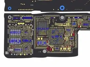
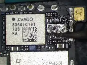
Open bitmap to confirm the position of PP_VDD_Main. Keep checking the signal board with the Thermal Imager. There is still no obvious change in the temperature. Through the bitmap, we see that PP_VDD_Main also exists under the card reader.
-
-
-
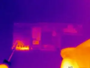
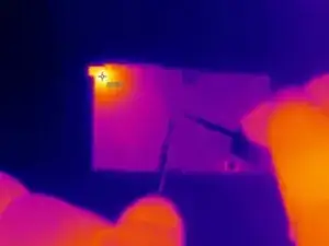
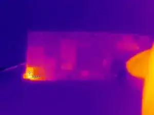
The faulty part is most likely hidden under the card reader. Then we check the back of the signal board with the Thermal Imager. The temperature on the top left corner of the card reader has gone up greatly. We can confirm that the faulty part is on the card reader area.
-
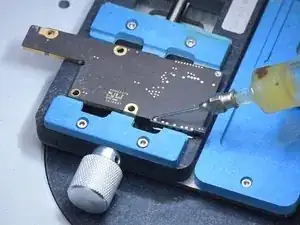
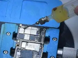
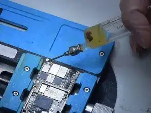
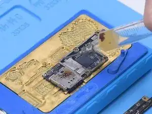
Then we need to remove the card reader. Apply some Paste Flux to the bonding pad of the card reader. To protect the plastic part of the card reader, apply some low-temperature Solder Paste to neutralize the temperature of the bonding pad.
-
-
-
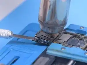
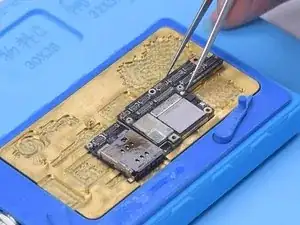
Next, use helical wind Hot Air Gun at 340 °C to heat the card reader. Try to pry up the card reader with a Pry Blade while heating. When the card reader becomes loose, remove the card reader.
-
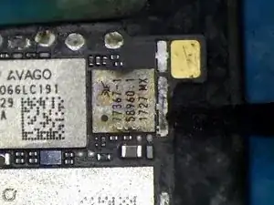
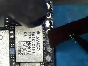
Keep checking the card reader area with the Thermal Imager. The temperature of the card reader area shows significant change. Judging from the bitmap, the part that gets hot is the GSM. Then we need to replace the GSM.
-
-
-
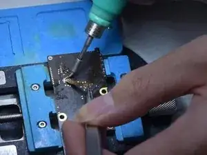
Apply some Paste Flux. Remove the GSM with vertical wind Hot Air Gun at 340 °C. Apply some Paste Flux and middle-temperature Solder Paste to the bonding pad. This is to lower the temperature of the bonding pad.
-
-
-
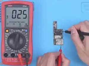
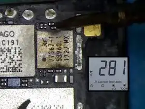
Clean the bonding pad with Hot Air Gun and Solder Wick. Then clean the bonding pad with PCB Cleaner. Measure the resistance value of PP_VDD_Main.
-
The resistance value returns to normal.
-
-
-
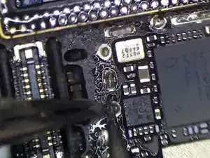
Then we install a known-good GSM. Apply some Paste Flux. Put the GSM in position. Solder with vertical wind Hot Air Gun at 320 °C.
-
After soldering, measure with multimeter again. The resistance value is normal.
-
-
-
Keep applying some low-temperature Solder Paste to the bonding pad of the card reader.
-
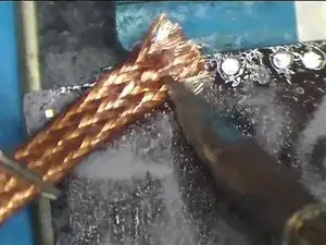
Clean the bonding pad with Hot Air Gun and Solder Wick. Then clean the back bonding pad with Soldering Iron and Solder Wick.
-
-
-
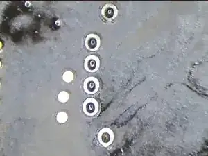
Next, clean with PCB Cleaner. It can be seen that the pins are clean.
-
Then we install the card reader. Put the card reader in position.
-
Solder the back bonding pad to fix the card reader with the Soldering Iron. Flatten excessive tin with Solder Wick. Please do not remove the tin while dragging the solder wick. Clean the bonding pad with PCB Cleaner.
-
-
-
Then we recombine the motherboard. Put the signal board on the 165 °C Heating Platform to heat. Apply some Paste Flux to the bonding pad. Align the logic board with the signal board. When the temperature reaches 165 °C, detach the motherboard.
-
For better recombination, press two sides of the motherboard gently with tweezers.
-
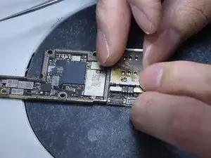
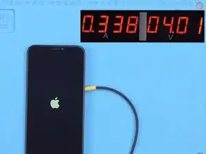
Then we power up the motherboard for testing. The current is normal.
-
-
-
Connect the screen to test. The boot current is also normal. The current leakage problem has been fixed.
-


To reassemble your device, follow these instructions in reverse order.