Introduction
-
-
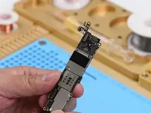
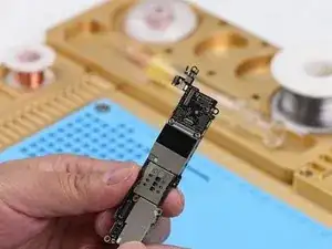
First, run cosmetic inspection of the logic board. The logic board bears no deformation or water damage issue.
-
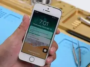
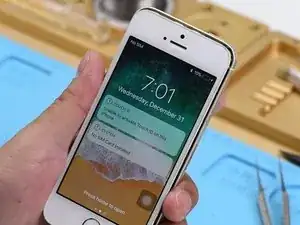
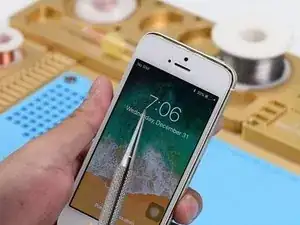
Next, let's assemble the phone and test. Get the logic board and display assembly installed. Connect the battery and press the power button. Battery percentage in the upper-right corner displays as 10%.
-
Plug in the charging cable. The lightning bolt shows up on the screen. After charging for 10 minutes, battery percentage in the upper-right corner still displays as 10%, which indicates that the charging circuit has malfunctioned.
-
-
-
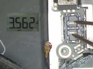
Switch the Multimeter to DC voltage mode. Disconnect the battery first. Then measure the battery connector J2400. The voltage jumps from 1V to 3.9V, then 1V, back and forth, which indicates that the charging voltage is normal.
-
-
-
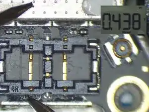
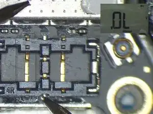
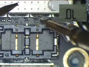
Disconnect the charging cable and remove the display assembly. Run diode mode measurement of J2400. The measured value of Pin 5 is 436, which is normal. The measured value of Pin 2 is OL, which is abnormal. Normal value should be around 600. Judging by this, Pin 2 relevant circuit has been open-circuited.
-
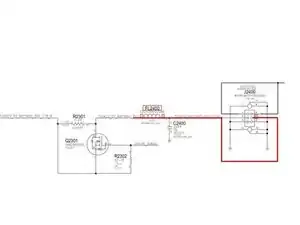
Pin 2 of J2400 is the battery percentage detect signal of the phone, which connects to Pin 3 of Q2301 by way of FL2400. The rail extends to Pin F2 of U2300 by way of Pin 1 of Q2301 and then R2303. Also when we are measuring, we find that FL2400 is missing.
-
-
-
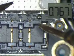
Continue to run diode mode measurement of its bonding pad. The measured value of Pin 2 is OL, which is normal. The measured value of Pin 1 is 767, which is normal. We can confirm now that the open-circuited condition is caused by missing FL2400.
-
-
-
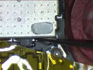
Since FL2400 is a coupled inductor, we can fix the problem by connecting the two pins with Solder Paste. Now, let's take out the logic board. Stick High Temperature Protective Tape on J2400.
-
Apply low-temperature Solder Paste to the bonding pad of FL2400. Heat with Hot Air Gun at 240℃, air flow 2. Then connect the two pins with melted Solder Paste. Wait for the logic board to cool for 5 minutes. Clean with PCB Cleaner afterwards.
-
To reassemble your device, follow these instructions in reverse order.