Introduction

The Razer Viper Mini may experience faulty trigger switch operation, such as a stuck button or having an unresponsive mouse button. This guide will show you how to access the trigger switches for cleaning or replacement.

  1. OSl4nnB5tWfQo5de
    OSl4nnB5tWfQo5de
    aj4X1KX1ORMAIHvI
    • Opening the mouse casing will void any warranty that exists for the mouse.

    • Make sure to unplug the mouse before doing anything.

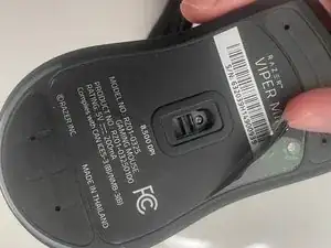
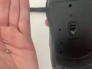
    • Turn the Mouse Over so the bottom is facing up.

    • Remember to take a photo of your serial number or write it down

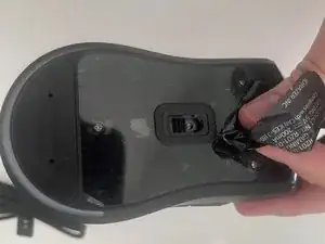
    • Take off the information sticker and the plastic cover from the bottom of the mouse.

  2. WsVvRXvEevvTnRCl
    WsVvRXvEevvTnRCl
    npof3DPf4rwB6gqm
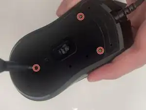
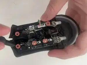
    • Use the Phillips #0 screwdriver to remove the three 2 mm screws from the bottom of the mouse.

    • When removing the screws, unscrew them each slightly and consecutively until you can pull them out with your hands.

  3. eAWYbvRuIIuVFXf4
    eAWYbvRuIIuVFXf4
    cTJ1oySKRXJ3hutp
    hBLna2stPpoyuKM2
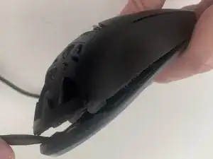
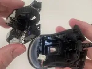
    • Use the plastic spudger to gently lift the backplate from the mouse shell.

    • Insert the spudger into the bottom back of the mouse and slowly move it around the mouse to release the backplate.

    • Do not try to push or jab the mouse with the plastic spudger with a large amount of force, this can damage the plating of your mouse.

  4. EZVlBOYyJg36MmZP
    EZVlBOYyJg36MmZP
    y1KLqWJegLHtLAin
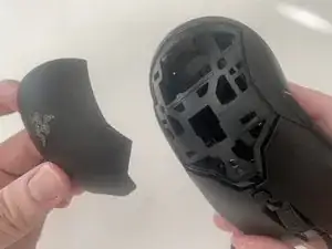
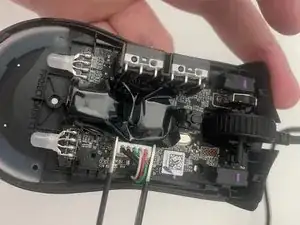
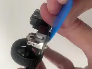
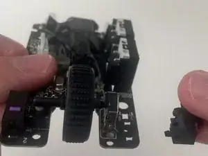
    • Use the plastic spudger once again to remove the top shell of the mouse.

    • It is similar to the previous step, as you have to pry the plastic spudger gently into the bottom of the mouse and move it slowly inwards and upwards to release the shell.

    • Separating the casing too quickly could damage the ribbon connector between the motherboard and the cable.

  5. HQtoeQVHydTJKtgv
    HQtoeQVHydTJKtgv
    NTJDALAwjAyoUbRA
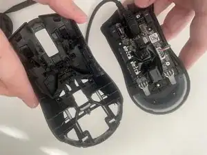
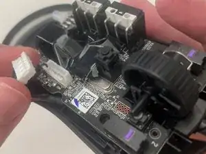
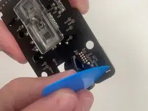
    • Disconnect the ribbon connector between the motherboard and the USB cable by squeezing the connector and pulling up.

    • Pulling too hard could damage the wire connections.

    • Pulling by the ribbon instead of the connector can dislocate the wires.

  6. MWQOsqSa5bB5tCLx
    • Use a Phillips #0 screwdriver to remove 2 5.5 and 3 2.5 mm screws.

  7. qUMPkql2jeB5ssa6
    • Remove the motherboard by grasping the sides and gently pulling upward.

  8. JvAjBQJCZuxCiuDM
    JvAjBQJCZuxCiuDM
    jhBNoJPFi4kSuxqe
    • Press the connectors upwards to remove the left switch from the PCB.

  9. HQK6nKKRwWYoaRAB
    HQK6nKKRwWYoaRAB
    KWPAiyPtFmqWXsdq
    • Press the connectors upwards to remove the Right switch from the PCB.

Conclusion

To reassemble your device, follow these instructions in reverse order.

Addison

Member since: 30/08/19

2940 Reputation

0 comments