
Introduction
This guide will show you how to replace the left and right micro switches for the Razer Mamba RC30-001201. Micro switches do not last forever and whether worn out through use, or by being faulty, they need replacing if you plan to keep using them. This guide will show you how to replace the two most used micro switches. The model number for the micro switches is D2FC-F-7N2CM.
-
-
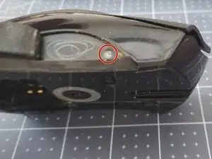
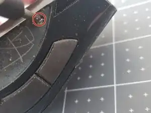
Remove one screw from the bottom of the mouse beneath the mouse foot using a Phillips #00 screwdriver.
-
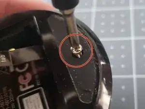
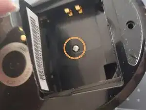
Remove one screw from the bottom of the mouse in the battery compartment using a Phillips #00 screwdriver.
-
-
-
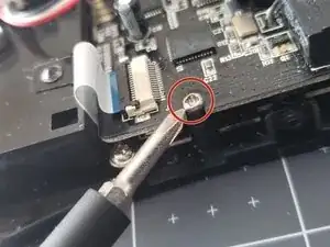
Remove the screw holding the right side of the board down using a Phillips #00 screwdriver.
-
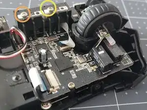
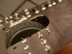
Remove the screw holding side micro switch using a Phillips #00 screwdriver.
-
Remove the screw holding the front side micro switch using a Phillips #00 screwdriver.
-
-
-
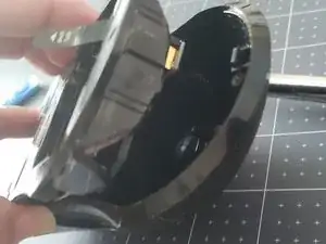
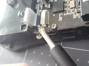
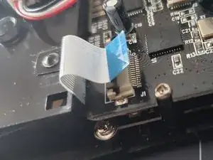
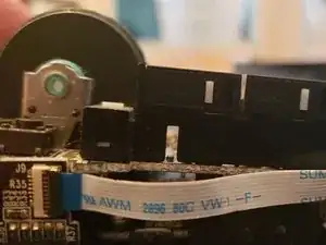
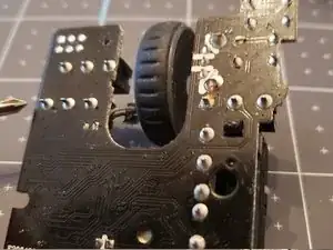
Disconnect the ribbon cables.
-
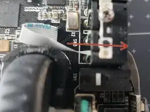
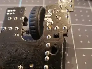
The second cable must also be routed through the side micro switch housing to get it out.
-
-
-
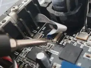
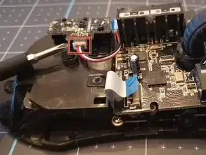
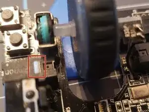
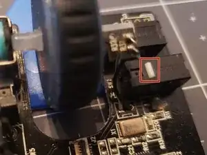
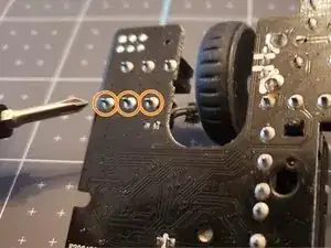
Find the faulty or worn out micro switches. This is the left micro switch.
-
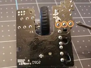
Desolder these pins to remove the micro switch.
-
-
-
Place the new switches in place one at a time.
-
Bend the pins outward slightly to help keep the switch in place, or use a tool like a forceps or a clamp to keep the micro switch from moving.
-
-
-
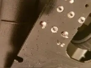
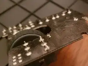
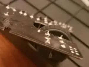
Solder the pins for the new micro switch to the board.
-
Get your iron up to temp. 400C degrees.
-
Tin your iron by placing a small amount of solder on the tip of the iron.
-
Heat up the joint by placing the tip of your iron against the intersection of base of the circuit pad, and pin [joint]. After 3-5 seconds it should be sufficiently heated.
-
Continue to hold the soldering iron on the pad, and pin and touch your solder to the joint.
-
A well made joint is smooth and shiny. A cone shape, like a volcano. Repeat process for other pins.
-
To reassemble your device, follow these instructions in reverse order.