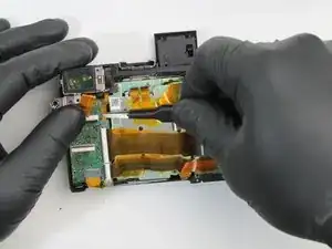
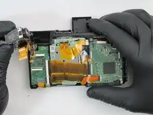
Introduction
Tools
-
-
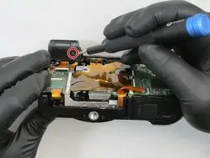
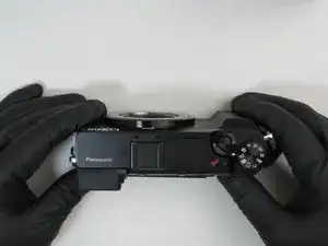
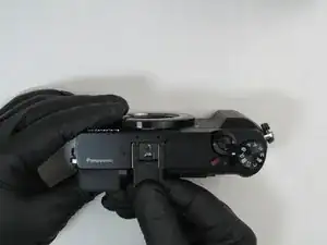
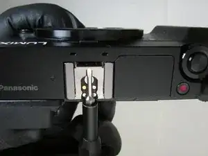
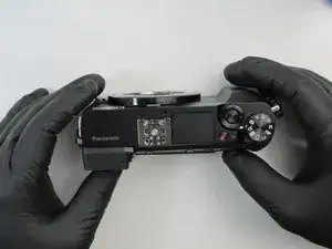
Using a spudger, gently lift the forward end of the shoe spring to disengage its locking mechanism.
-
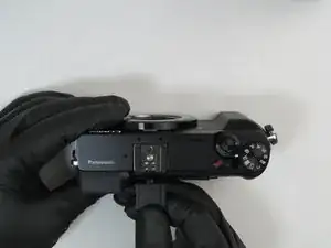
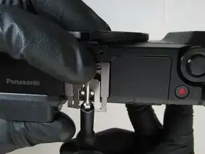
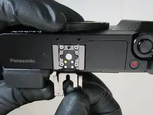
While holding the forward end of the shoe spring up, push from its lifted end to remove the shoe spring.
-
-
-
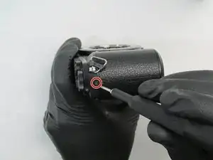
Turn the camera so the side with the jack cover is facing you.
-
Near the camera's top end, remove the 4.0mm black Phillips #0 screw on the bottom in this orientation.
-
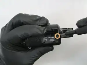
Open the jack cover and remove the 4.0mm black Phillips #0 screw inside.
-
-
-
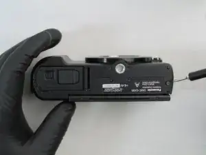
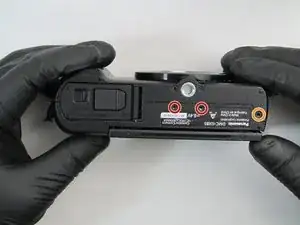
Flip the camera upside down so the bottom of the camera is facing you.
-
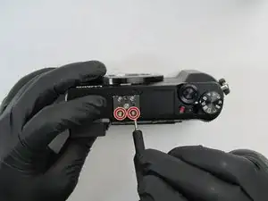
Remove the two center 2.5mm black Phillips #0 screws.
-
Remove the outer 4.5mm black Phillips #0 screw.
-
-
-
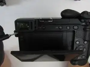
Turn the camera so the display screen is facing you.
-
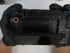
Rotate the top of the screen away from the camera body to access and remove the 4.5mm black Phillips #0 screw.
-
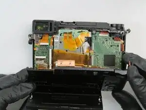
Remove the rear camera cover by gently pulling from the top side.
-
-
-
Turn the camera so the lens is facing down with the rear cover pulled back.
-
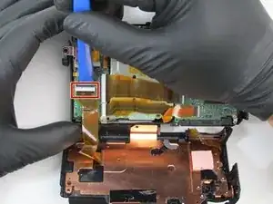
Disconnect the ribbon cable from the camera by pulling up on the black locking tab with an iFixit opening tool.
-
Pull the ribbon cable from the connector. The rear cover is now completely detached from the camera.
-
-
-
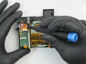
Remove the 4.5mm black Phillips #0 screw under the viewfinder.
-
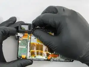
Gently pull the viewfinder cover from the camera.
-
-
-
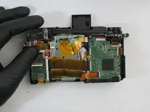
Remove the 2.5mm silver Phillips #0 screw located below the viewfinder.
-
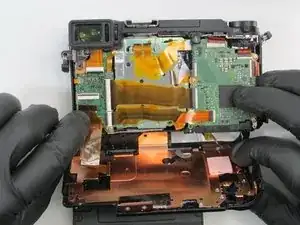
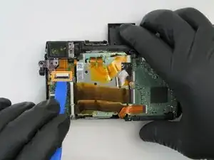
Remove the ribbon cable from the underside of the camera by unlatching the black locking tab with an iFixit opening tool then pulling the ribbon away from the connector.
-
-
-
Remove the small ribbon cable by gently pulling it away from the camera with ESD safe tweezers.
-
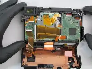
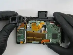
Remove the viewfinder from the camera body.
-
To reassemble your device, follow these instructions in reverse order.
One comment
Is it possible to just remove the viewfinder cover seen on step 8 without anything else? (Provided that I have a screwdriver with a flexible end that can fit in there without messing the screen up). Thanks.
