Introduction
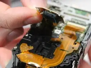
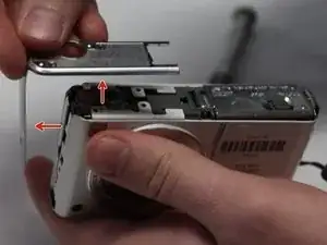
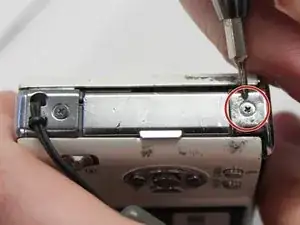
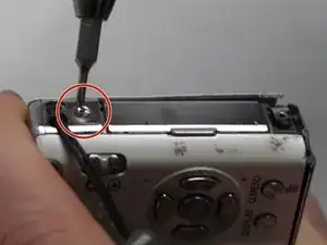
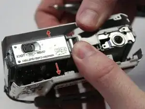
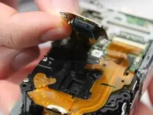
This guide will show you how to access and remove the photoreceptor from the camera. It features three ribbon cables that you should handle carefully due to their delicate nature. As always, you should take note as to what screws go where so that you do not cause internal damage to your device.
Tools
Parts
-
-
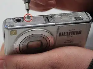
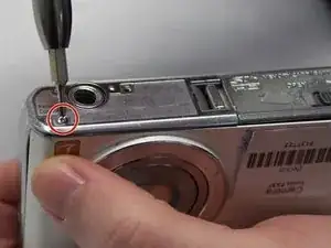
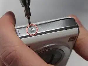
On the opposite side of the camera, remove the two 3 mm screws.
-
Remove the bottom side panel and place it with its respective 3 mm screw.
-
-
-
Remove the front panel (the panel around the lens casing) from the camera.
-
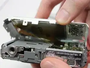
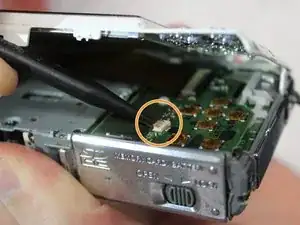
Remove the two ribbon cables connected to the back panel (the panel this the LCD screen) by lifting up on their respective tabs and gently pulling out the cord.
-
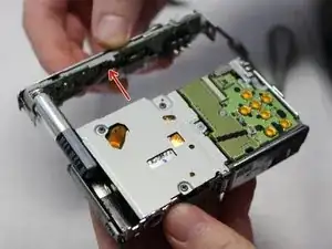
Remove the back panel from the camera.
-
-
-
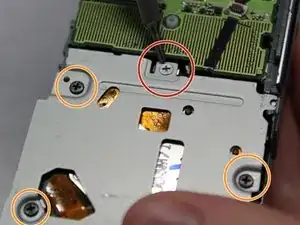
Locate and remove the silver 2mm screw on the protection panel.
-
Remove the three black 8mm screws that remain.
-
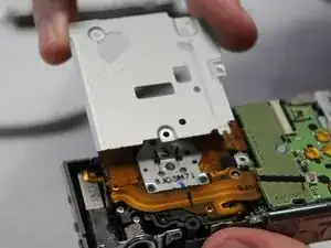
Proceed to remove the protection panel entirely.
-
-
-
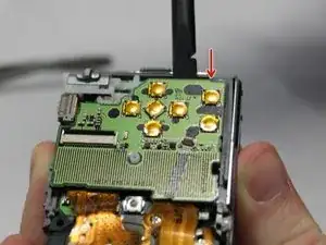
Insert the flat end of a plastic spudger underneath the motherboard and twist. This will disconnect the board from the device and allow it to be removed.
-
-
-
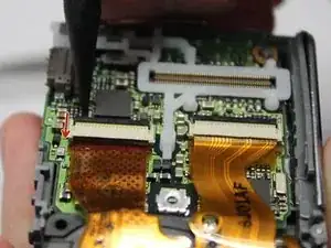
Use the pointed end of the spudger to lift the black tabs holding the ribbon cable connected to the photoreceptor in place.
-
-
-
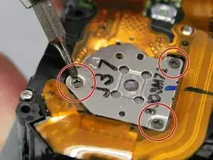
Remove the three 3mm screws holding the photoreceptor in place.
-
Carefully lift the photoreceptor, disconnecting the ribbon cable and remove the photoreceptor from the device.
-
To reassemble your device, follow these instructions in reverse order.
