Introduction
This guide will show you how to almost completely strip down your device. Because of this, it may take a fair bit of time if you have never done a disassembly before. If you are looking for a guide to access the lenses themselves, this guide will not show that. However, it is possible if you have the patience to disassemble the lens casing.
-
-
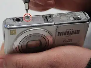
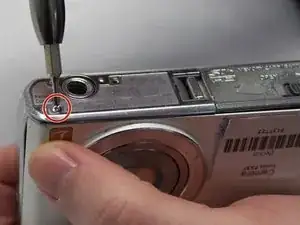
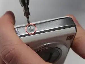
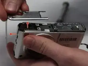
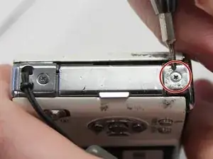
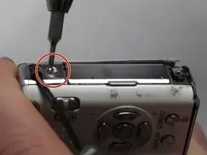
On the opposite side of the camera, remove the two 3 mm screws.
-
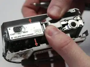
Remove the bottom side panel and place it with its respective 3 mm screw.
-
-
-
Remove the front panel (the panel around the lens casing) from the camera.
-
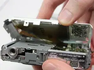
Remove the two ribbon cables connected to the back panel (the panel this the LCD screen) by lifting up on their respective tabs and gently pulling out the cord.
-
Remove the back panel from the camera.
-
-
-
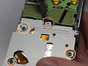
Unscrew the silver 2mm screw from the protection panel.
-
Unscrew the three black 8mm screws from the protection panel.
-
Remove the protection panel entirely.
-
-
-
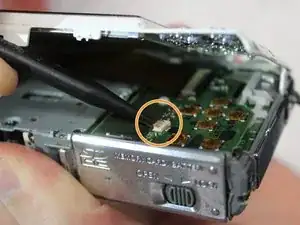
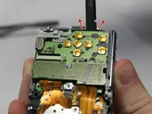
Insert the flat end of a spudger underneath the motherboard and twist. This will disconnect it from the rest of the device.
-
-
-
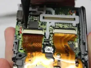
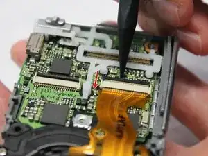
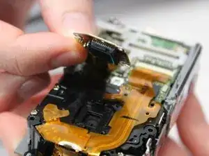
Using the pointed end of a spudger, flip up the two black tabs holding the ribbon cables in place.
-
-
-
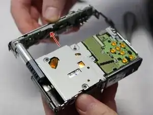
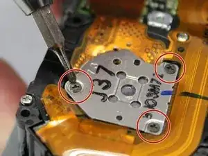
Unscrew the three 3mm screws holding the photoreceptor in place.
-
Lift the photoreceptor and gently pull it to release the now disconnected ribbon cable.
-
-
-
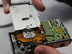
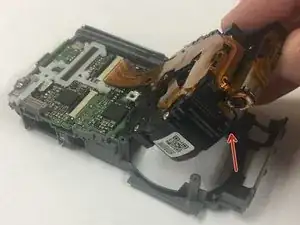
Gently lift and remove the lens casing, pulling it free from the now disconnected ribbon cable.
-
To reassemble your device, follow these instructions in reverse order.