Introduction

This guide will be useful for anyone who wants to replace a broken or damaged Panasonic Lumix DMC-FX01 lens assembly.

  1. AFHAgVcOa2VkX6rq
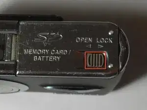
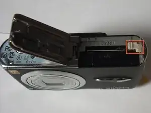
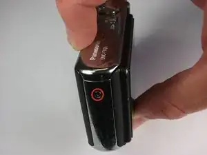
    • Locate the memory card and battery card latch on the bottom of the camera.

    • Slide the latch to the open position.

  2. DaC4xP1oNRDSJFuP
    • Open the battery latch, and slide the battery release lever to the right.

  3. IuAgNtphQpXZgbOw
    • Remove the battery from the camera.

  4. HZWy5DZCtaf3K4oM
    • Remove the three 4.6 mm screws on the bottom of the camera using a Phillips #00 screwdriver.

  5. pZalWsmMJDkXNcZL
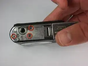
    • Remove the single 3.2 mm screw on the left side of the camera using a Phillips #00 screwdriver.

  6. 4CHFUKhQHVjVdbHI
    4CHFUKhQHVjVdbHI
    FxQ6mCETMtTdgil6
    • Remove the left side casing.

  7. buDLx5ofwLWpYNMT
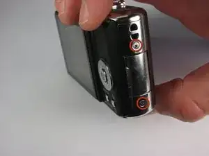
    • Remove the two 3.2 mm screws on the right side of the camera using a Phillips #00 screwdriver.

  8. MSSdvXFH1UO2Tnli
    • Remove the bottom right panel.

  9. bCDk6feXdHXExMLu
    bCDk6feXdHXExMLu
    3UjKjFOYHpwiY4Ca
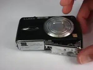
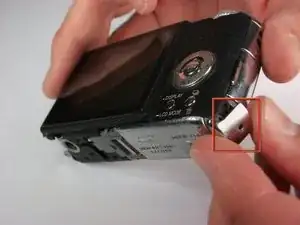
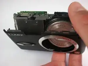
    • Gently remove the back casing.

    • Start at the bottom and carefully pry towards the top to get this piece free.

  10. B4XByOQUDRxHvZXc
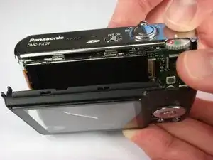
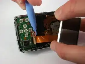
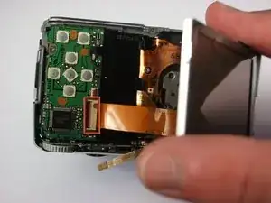
    • Gently lift up the LCD screen.

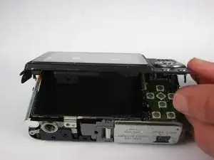
    • Using a plastic prying tool, flip up the latch that holds the thin ribbon in place.

    • It should fall out on its own or with a gentle tug.

  11. e1J4OB1XVNL2SgFv
    • Gently tug the thicker ribbon to remove it from its housing.

    Not sure i the author forgot to add this, but the black part of this connector is locking mechanism for the ribbon. Lifting it will help.

    Michal Andres -

  12. dcMWJUXqhoWea1Gy
    dcMWJUXqhoWea1Gy
    UP2Wa3cLxKlpQ2Ny
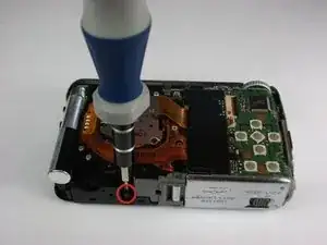
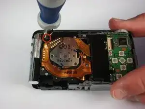
    • Remove the two black 5.4 mm screws that hold in the front faceplate using a Phillips #00 screwdriver.

    • There may be a third screw the the right of the lens assembly.

  13. K5TvyvAcgtGOPhQ6
    K5TvyvAcgtGOPhQ6
    wONXOqrqZnvkvrBm
    HUMxbaBRGgfvIK1V
    • Carefully remove the upper assembly, which houses the buttons and the flash battery.

  14. KXEvASPNPshGtuwa
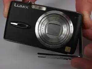
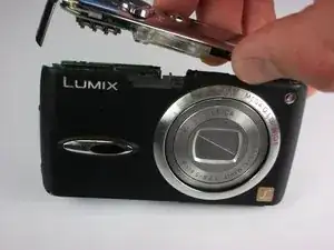
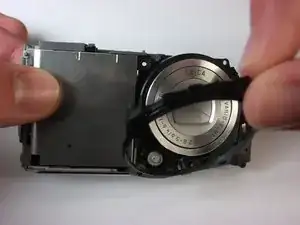
    • Carefully remove the front casing after verifying that the thin plastic around the lens is not still attached.

  15. PyQUCeiUIhZ2WgsP
    PyQUCeiUIhZ2WgsP
    ptG2NAvKSyGi3Auj
    • Remove the three black 5mm screws attached to the lens frame.

  16. rYVFraOfMV3ExkHd
    • Remove the lens frame.

  17. I5TnJjVFFAkXLCLQ
    • Lift out the circuit board as shown.

  18. iErV2fhrI1qSZ3AT
    iErV2fhrI1qSZ3AT
    HeYY5tbdpPugZjc3
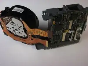
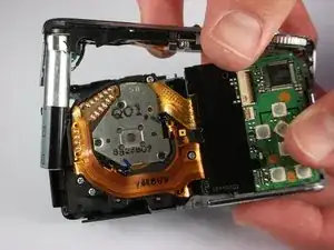
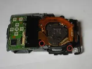
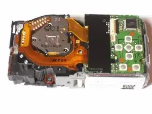
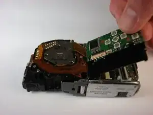
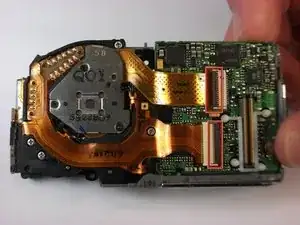
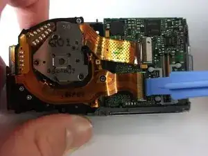
    • Lift the two black latches that hold the connector ribbons in place.

    • Disconnect the two ribbons.

  19. 3kcMHOWqZ6FhlARl
    • Remove the lens assembly as shown.

Conclusion

To reassemble your device, follow these instructions in reverse order.

Steven

Member since: 11/10/10

108 Reputation

0 comments