Introduction
If you’ve cracked the screen or are experiencing issues with the screen of your Panasonic Lumix DMC-F7 digital camera, it may be time for a replacement. To complete this replacement, you will need to know how to solder. You will also need a few tools, so be sure to check the Tools List below before starting this replacement. This guide will help you properly replace the LCD (liquid crystal display) screen for the Panasonic Lumix DMC-F7 digital camera.
-
-
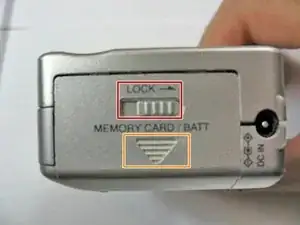
Slide the lock switch to the right so that it is in the unlocked position.
-
Use your finger to slide the battery hatch in the direction of the downward arrow so that the hatch is open.
-
-
-
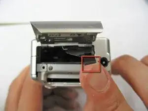
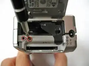
Open the battery hatch and then the black cover to expose the battery compartment.
-
Remove the battery.
-
-
-
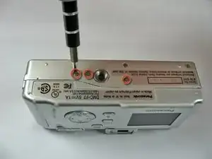
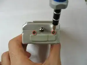
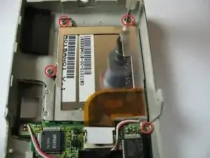
Use the Phillips #00 screwdriver to remove the three 2.8 mm screws on the bottom of the camera.
-
-
-
Place the camera on a flat surface with the front side facing down.
-
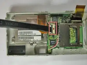
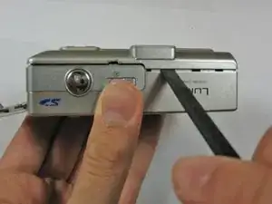
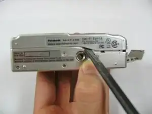
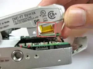
Use the spudger to flip up the retaining flap and slide the ribbon cable out of the connector.
-
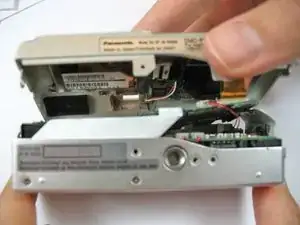
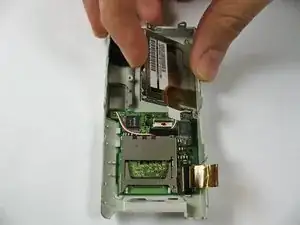
Hold down on the camera's metal casing with one hand. Using your other hand, remove the back case from the rest of the camera.
-
-
-
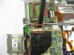
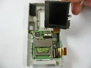
Use a spudger to lift the screen ZIF connector tab.
-
Use the back of the spudger to push the ribbon cable free.
-
-
-
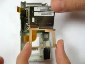
Use the screwdriver to remove the four 2.4 mm Phillips screws.
-
Lift up the LCD screen from the front case.
-
-
-
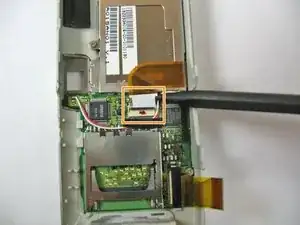
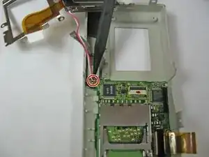
Locate the wire connecting the LCD screen to the motherboard.
-
Use the soldering iron to desolder the wire.
-
Use the soldering iron to solder wires from new LCD screen to the circuit board.
-
To reassemble your device, follow these instructions in reverse order.